
 Distribution PL · 4REF
Wipcool TV-15 user manual
Read the entire manual before first use. Keep it for as long as you use the device.
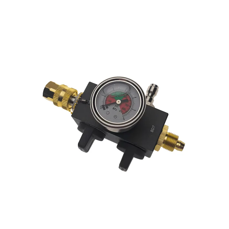
Wipcool TV-15 user manual
The Wipcool TV-15 valve is used for hydraulic leak testing of pipework at pressures up to 15 bar. It works with a pressure washer.
The user manual is an integral part of the product. Please read this manual carefully and follow all instructions strictly.
General information
Wipcool products are designed for professional use by qualified air conditioning and refrigeration engineers. As the manufacturer, Wipcool stipulates that our products should only be operated by suitably qualified and trained persons.
- ■Comply with all local safety regulations and general safety standards when using the Wipcool TV-15 hydraulic pressure test valve.
- ■The user manual should be kept near the product so that personnel can access it easily at all times.
- ■Before use, qualified personnel should read the user manual carefully and understand all the instructions it contains.
- ■The manufacturer accepts no liability for any damage resulting from improper use, failure to follow the user manual, lack of personnel qualifications or any unauthorised modifications to the product.
- ■The general terms and conditions of sale contained in the sales documents apply.
Symbols and conventions
Symbols used in the manual:
- 01
 Warning - read the text in the box next to the symbol.
- 02
 Notice - risk of damage to the device or incorrect results.
Safety information
Check that the pressure washer connection matches the TV-15 inlet in terms of thread and seal.
Technical specifications
Device diagram
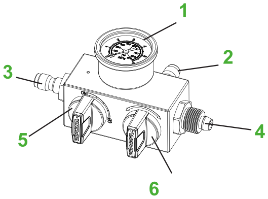
| No. | Name |
|---|---|
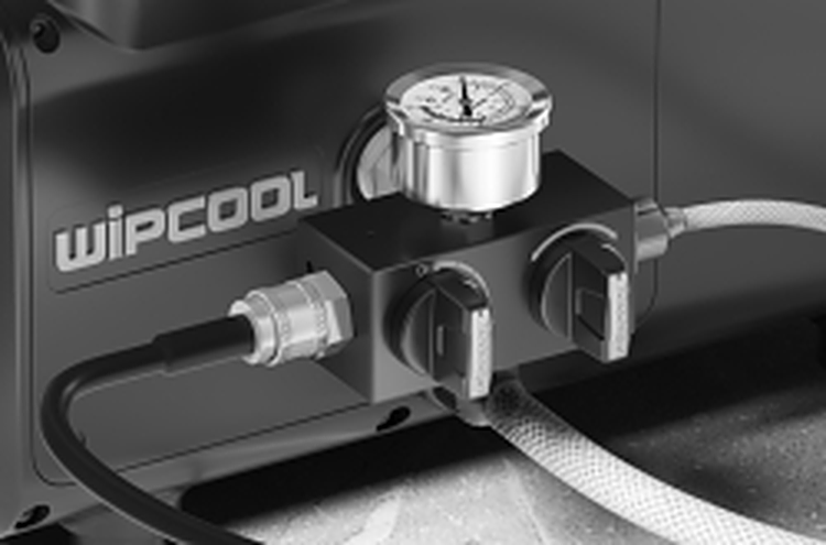
| 1 | Pressure gauge |
| 2 | Inlet - connection to pressure washer |
| 3 | Outlet - connection to system under test |
| 4 | Pressure relief connection |
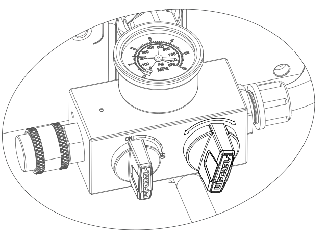
| 5 | ON/OFF valve - circuit isolation; ON - open, OFF - closed |
| 6 | REGULATING valve - pressure setting |
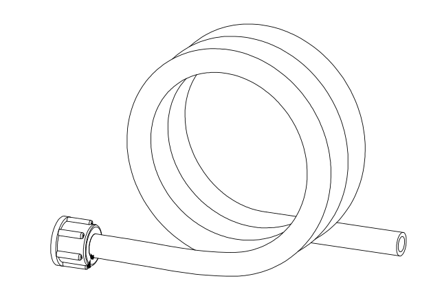
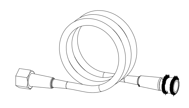
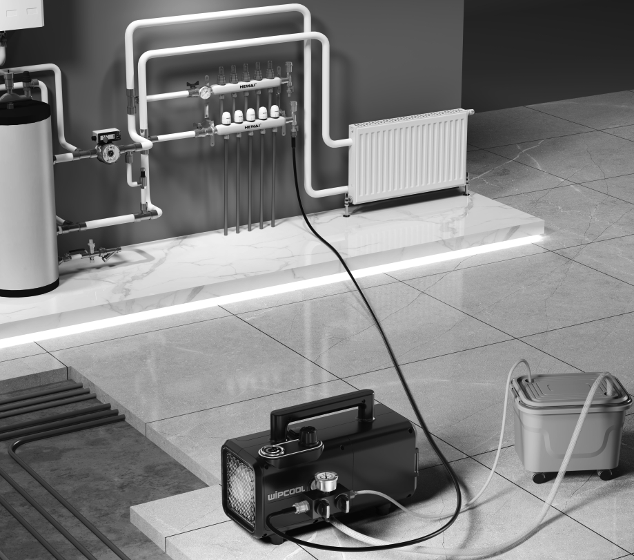
The relief hose connects the pressure relief connection to the water tank. The test hose connects the valve outlet to the system under test. The quick-release coupling plug closes the outlet during pressure adjustment.
Kit contents
After unpacking, check that the kit is complete and in good condition. Report any missing or damaged items to the seller.
- ■TV-15 valve.
- ■Quick-release coupling plug.
- ■User manual.
For the test, prepare a pressure washer with a suction hose, a water tank, a relief hose and a test hose.
Transport and storage
- ■Transport the valve in its original packaging.
- ■Store it in a dry place, away from direct sunlight and heat sources.
Application
The test is performed using water. The TV-15 is used for hydraulic testing of heating, compressed air, sprinkler and other small-diameter pipework systems.
The valve works with pressure washers with a 1/4" connection. Use a pressure washer with a flow rate of up to 5 l/min.
The quick-release coupling allows the pressure washer to be disconnected while the TV-15 remains in the circuit under test. The pressure washer can be used to test another circuit with a second TV-15 valve.
Connection
Before making connections, switch off the pressure washer and disconnect its power supply.
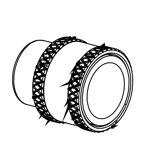
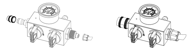
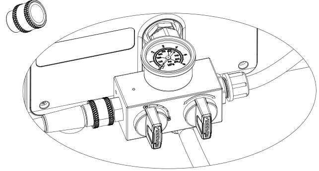
- 01Fit the quick-release coupling plug to the TV-15 outlet and connect the relief hose to the pressure relief connection.
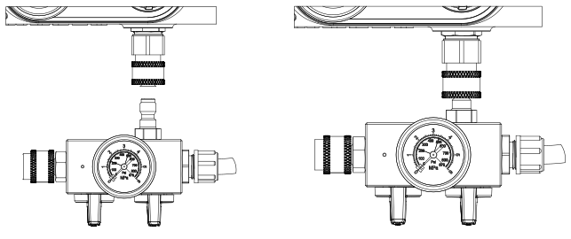
- ■2. Connect the TV-15 inlet to the pressure washer as shown. Check that the connection is secure and leak-tight.
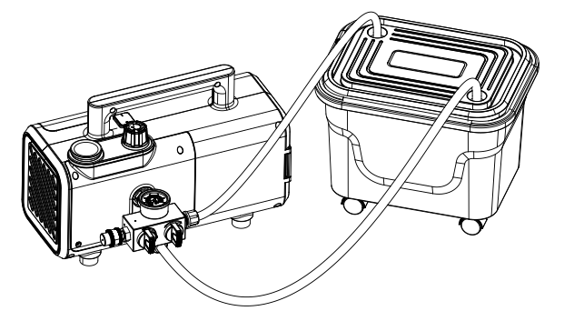
- ■3. Fill the tank with water and immerse the ends of the pressure washer suction hose and the relief hose in it. Check the connections.
Instructions for use
1. Pressure adjustment
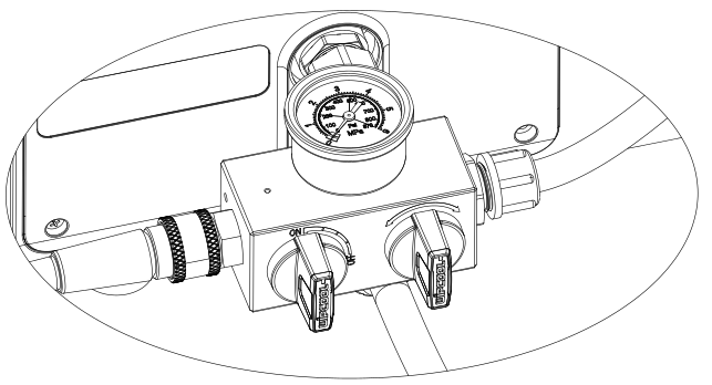
Open the ON/OFF valve and leave it in this position during adjustment. Connect the pressure washer to the power supply, start it and, while watching the pressure gauge, set the required test pressure by turning the REGULATING valve.
2. Connecting the test hose
Switch off the pressure washer and disconnect its power supply. When the pressure gauge reads 0 bar, remove the quick-release coupling plug and connect the test hose.
Check that the hose is securely attached and leak-tight, then connect it to the system under test.
3. Filling the system
Connect the pressure washer to the power supply and start it with the ON/OFF valve open, while watching the pressure gauge.
4. Isolation and leak test
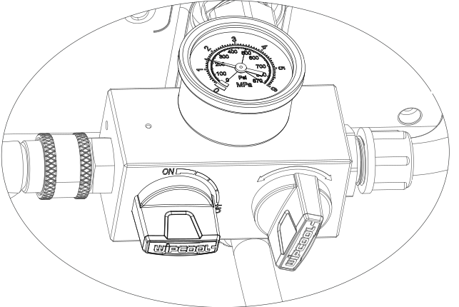
When the pressure gauge indicates the set pressure, close the ON/OFF valve by turning it to the OFF position. Immediately switch off the pressure washer and start the system leak test.
Troubleshooting
Before checking the connections, switch off the pressure washer and disconnect its power supply. Do not disconnect or adjust connections while they are under pressure.
| Problem | Possible cause | Solution |
|---|---|---|
| Pressure does not increase | No water supply, incorrect REGULATING valve setting or a leak | Check the water supply and pressure washer operation. Check the REGULATING valve setting and the connections for leaks. |
| Pressure exceeds the permitted value | Incorrect selection or settings of the kit | Switch off the pressure washer. Before the next test, check the pressure washer selection and pressure setting; take into account the lowest permitted pressure of the kit components. |
| Leak at a connection | Incompatible connection, incorrect seating or damaged seal | Stop the test and switch off the pressure washer. Check the compatibility and seating of the connection and the condition of the seal. Carry out the check with the system depressurised. |
| Damaged pressure gauge or unreliable reading | Pressure gauge damage | Stop the test. Do not assess leak-tightness based on an uncertain reading. Arrange for repair by the service centre - submit a request at wipcool.pl/serwis. |
Service and documents
Before submitting a request, have the following ready:
- ■Model - shown on the product nameplate and invoice.
- ■Serial number - if there is none, provide the production number (e.g. 11/2025), usually found on the underside of the product.
- ■Proof of purchase - an invoice or receipt from an authorised distributor.
- ■Fault description - what is happening, since when and under what conditions.
You can submit a service request at wipcool.pl/serwis. You will also find the warranty terms there.