
 Distribution PL · 4REF
Wipcool MG-2K user manual
Read the entire manual before first use. Keep it for as long as you use the device.
Wipcool MG-2K user manual
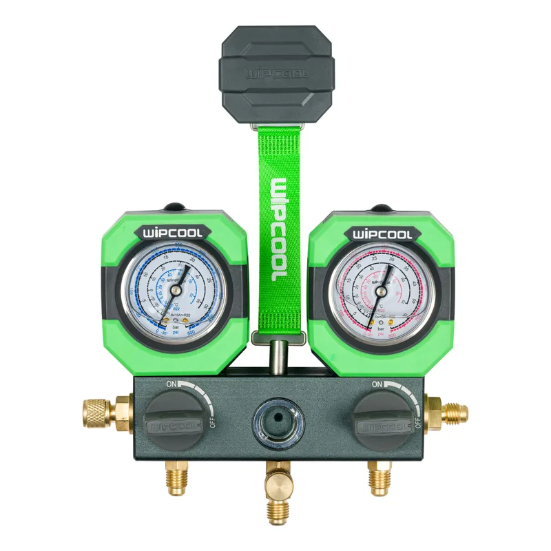
The MG-2K is an analogue manifold gauge set for measuring pressure, evacuating and charging refrigeration systems. The gauge scales also allow you to read the evaporation temperature corresponding to the pressure of a given refrigerant.
The user manual is an integral part of the product. Please read this manual carefully and follow all instructions strictly.
General information
Wipcool products are designed for professional use by qualified air conditioning and refrigeration technicians. As the manufacturer, Wipcool stipulates that our equipment should only be operated by appropriately qualified and trained personnel.
- ■Observe all local safety regulations and general safety standards when using the Wipcool MG-2K manifold gauge set.
- ■Keep the user manual near the equipment so that personnel can easily access it at all times.
- ■Before use, qualified personnel should read the user manual carefully and understand all the instructions it contains.
- ■The manufacturer accepts no liability for any damage resulting from improper use, failure to follow the user manual, lack of personnel qualifications or any unauthorised modifications to the equipment.
- ■The general terms and conditions of sale contained in the sales documents apply.
Symbols and conventions
Signs and markings used on the equipment and in the manual:
- 01
 Warning - read the text in the box next to the symbol.
- 02
 Low temperature - risk of frostbite on contact with refrigerant.
- 03
 Indicates that the product meets the health, safety and environmental standards applicable in the European Union.
- 04
 Do not dispose of the manifold gauge set with household waste.
Safety information
If refrigerant gets into your eyes, immediately flush them with plenty of water and consult a doctor.
- ■Use only refrigerants compatible with the markings on the manifold gauge set.
- ■Do not use excessive force to open or close the valves - this can damage the seal.
- ■Protect the set from harmful and corrosive substances, particularly ammonia.
- ■Do not release refrigerant into the atmosphere. Recover residual refrigerant from the hoses and manifold gauge set using a refrigerant recovery machine.
Technical specifications
Device diagram
LP denotes the low-pressure side and HP denotes the high-pressure side. LED denotes the gauge backlight and USB-C denotes the charging port.
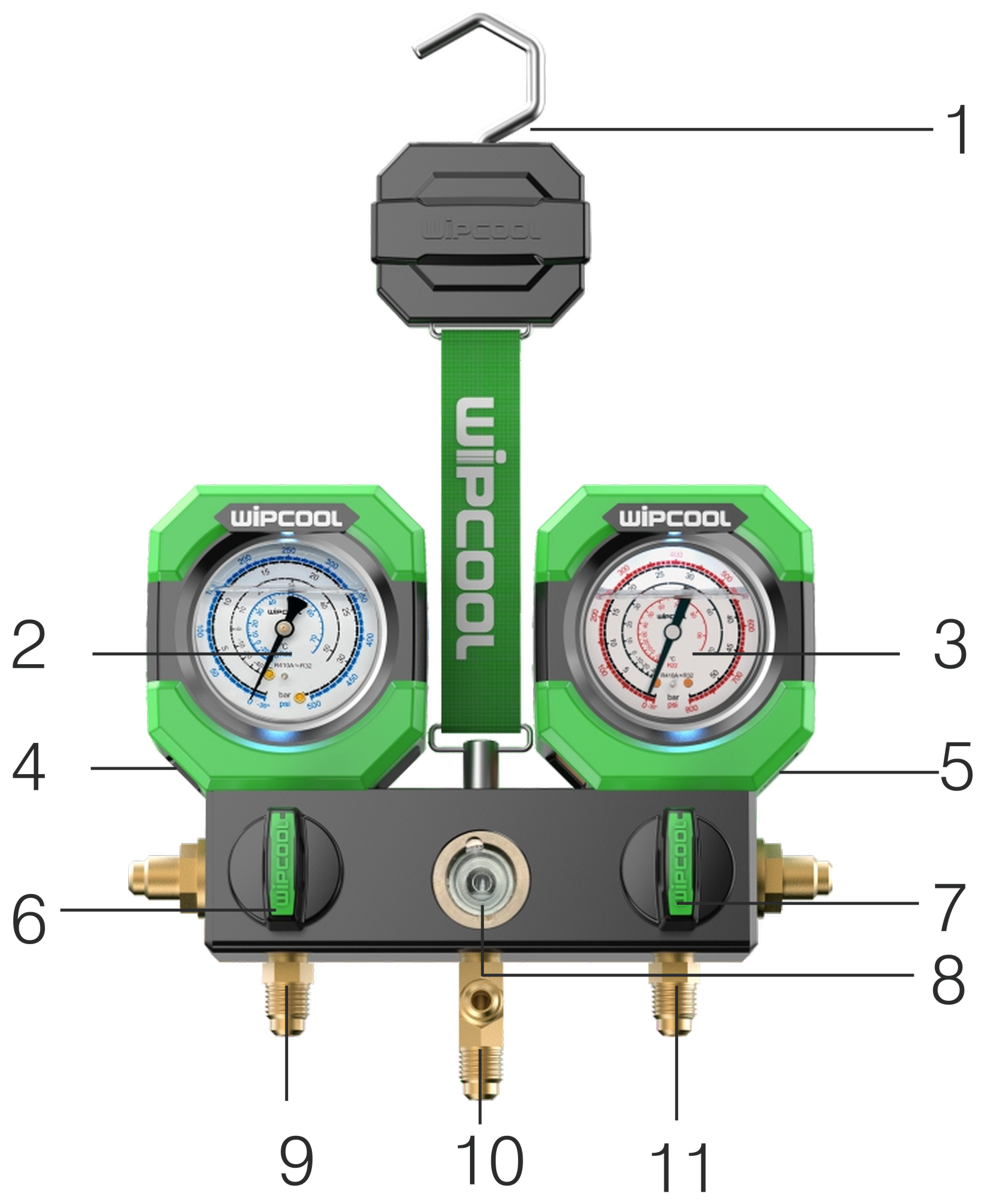
| No. | Name |
|---|---|
| 1 | Hook |
| 2 | Low-side gauge (also measures vacuum) |
| 3 | High-side gauge (also measures vacuum) |
| 4 | USB-C port |
| 5 | LED button |
| 6 | Low-pressure valve knob |
| 7 | High-pressure valve knob |
| 8 | Sight glass |
| 9 | Low-pressure hose connection |
| 10 | Centre connection (yellow hose) |
| 11 | High-pressure hose connection |
Contents of the set
After unpacking, check that the set is complete and in good condition. Report any missing or damaged items to the seller.
| Item | Quantity / description |
|---|---|
| MG-2K manifold gauge set | 1 pc. |
| Yellow hose | 1 pc., 1.5 m, 1/4" - 1/4" |
| Red hose | 1 pc., 1.5 m, 1/4" - 5/16" |
| Blue hose | 1 pc., 1.5 m, 1/4" - 5/16" |
| Adapters | 2 pcs., 5/16" MFL - 1/4" FFL |
| Bag | 1 pc. |
| User manual | 1 pc. |
Transport and storage
- ■Transport the set in its original packaging. Protect it from vibration and falls.
- ■Store the set in a dry place, away from direct sunlight and heat sources.
Connection
A vacuum pump, refrigerant cylinder and refrigerant charging scale are additional equipment required for the procedures described.
Before connecting, check that the gauges read zero. Before each use, inspect the condition of the hoses and check that seals are present in their connections.
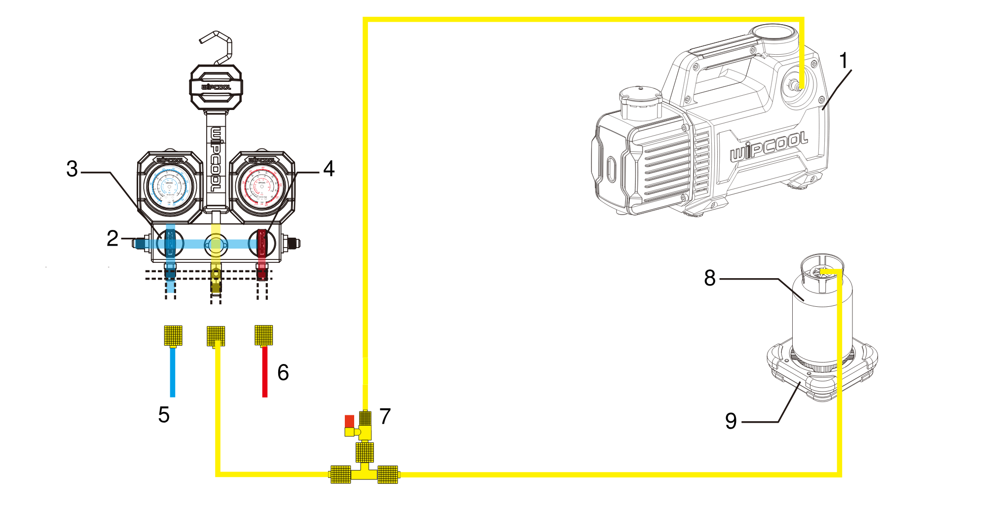
| No. | Item in diagram |
|---|---|
| 1 | Vacuum pump |
| 2 | Air purge port |
| 3 | Low-pressure valve |
| 4 | High-pressure valve |
| 5 | To the system low-pressure service port |
| 6 | To the system high-pressure service port |
| 7 | T-piece with shut-off valve |
| 8 | Refrigerant cylinder |
| 9 | Refrigerant charging scale |
Connect the blue hose only to the low-pressure side and the red hose to the high-pressure side. Connect the yellow hose to the centre connection.
Operation
Pressure measurement
- 01Close both valves on the manifold gauge set. Connect the blue hose to the system low-pressure service port and the red hose to the high-pressure service port.
- 02Start the system and read both gauges.
- 03After completing the measurement, switch off the system.
System evacuation
- 01Close both valves on the manifold gauge set. Connect the blue hose to the system low-pressure service port, the red hose to the high-pressure service port and the yellow hose to the vacuum pump.
- 02Open both valves on the manifold gauge set and switch on the vacuum pump.
- 03Monitor the low-side gauge reading for 3–5 min. Once the required vacuum is reached, close both valves, then switch off the vacuum pump.
- 04For a further 3–5 min, check that the low-side gauge needle remains at approximately -1 bar (-30 inHg on the scale). If it does not, repeat steps 2–3.
Topping up refrigerant
The following steps apply to topping up refrigerant in a system that has already been charged.
- 01Close both valves on the manifold gauge set. Connect the blue hose to the system low-pressure service port and the red hose to the high-pressure service port. Start the system and after approximately 5–10 min check the pressure on both sides.
- 02If the pressure is too low, close both valves on the manifold gauge set and connect the yellow hose to the refrigerant cylinder. Draw R410A in liquid phase: from a cylinder inverted with the valve pointing downwards or from a cylinder with a dip tube.
- 03Open the cylinder valve and purge the yellow hose.
- 04With the compressor running, slowly open the low-pressure valve and add refrigerant in small amounts on the suction side. Monitor the amount of refrigerant using the scale and the pressure using the gauges.
- 05After adding the required amount of refrigerant, close the low-pressure valve and the cylinder valve, then check the system pressure again. If it is still too low, open the cylinder valve and repeat steps 4–5.
Maintenance
General recommendations
Replace hoses if worn or damaged. Have the gauges calibrated every 3–6 months.
Charge the built-in backlight battery regularly through the USB-C port.
Cleaning
- ■Clean the gauge surfaces and copper connections with a damp cloth. Use a mild detergent if necessary. Do not use strong alkaline or acidic agents.
- ■After recovering residual refrigerant from the set, open the valve and blow out any contamination with compressed air.
Waste electrical and electronic equipment
- 01The crossed-out bin symbol means that the equipment must not be disposed of with other waste at the end of its life.
Under the applicable regulations on waste electrical and electronic equipment, products marked with the separate collection symbol must not be disposed of with other municipal waste. Because they contain harmful substances, electronic products that are not collected separately may pose a risk to the environment and human health. Proper separate collection of waste electrical and electronic equipment prevents adverse effects on the environment.
By taking waste equipment to a collection point, you contribute to its reuse, recycling and recovery.
Recycling - a method of protecting the environment. The process of recovering substances from waste that can be reused as raw materials.
Waste recovery - the use of waste that has lost its useful value, such as plastics, paper and cardboard, as secondary raw materials (also commonly understood as destruction).
Information on the collection system for waste electrical and electronic equipment
- ■Waste electrical and electronic equipment must not be disposed of with other waste.
- ■The collection of incomplete electrical and electronic equipment and parts from waste equipment is prohibited.
- ■A distributor supplying equipment intended for households to a purchaser must collect waste household equipment free of charge at the place of delivery, provided that the waste equipment is of the same type and performs the same function as the equipment supplied.
- ■You can hand over waste equipment to a waste equipment collector, a treatment facility or a municipal waste collector in your municipality.
- ■Information about collection points is available on the public information bulletin (BIP) websites of regional, city and municipal offices.
Batteries and rechargeable batteries
- 01The crossed-out bin symbol on a battery or rechargeable battery means that it must be collected separately from other waste at the end of its life. It must not be disposed of with municipal waste.
- ■Take used batteries and rechargeable batteries to a collection point. If possible, remove them from the device before taking it for collection.
- ■Substances contained in batteries can harm the environment and health, especially if a battery is damaged or leaking. Separate collection allows them to be processed safely and raw materials to be recovered.
- ■The Cd or Pb marking below the bin symbol means that the battery contains more than 0.002% cadmium or more than 0.004% lead.
The MG-2K set has a built-in battery - do not remove it yourself. Take the set to a collection point with the battery in place.
Service and documents
Before submitting a service request, prepare:
- ■Model - found on the equipment nameplate and on the invoice.
- ■Serial number - if there is none, provide the production number (e.g. 11/2025), usually found on the underside of the equipment.
- ■Proof of purchase - an invoice or receipt from an authorised distributor.
- ■Description of the fault - what is happening, since when and under what conditions.
You can submit a service request at wipcool.pl/serwis. You will also find the warranty terms there.