
 Distribution PL · 4REF
Wipcool P22i user manual
Read the entire manual before first use. Keep it for as long as you use the device.
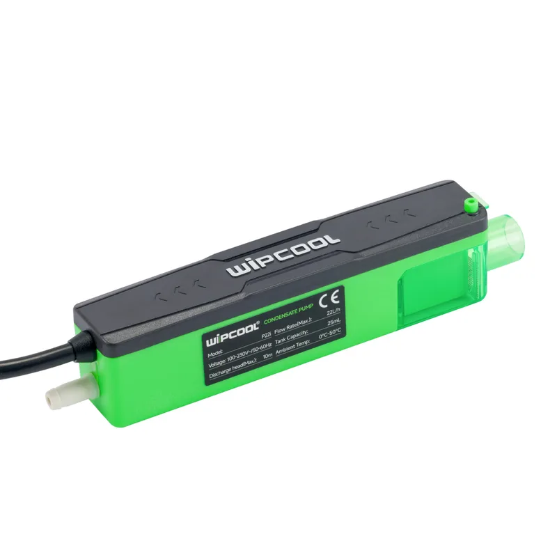
Wipcool P22i user manual
The Wipcool P22i condensate pump is designed to drain condensate from air conditioners. It has a tank integrated into the housing.
The user manual is an integral part of the product. Please read this manual carefully and follow all instructions strictly.
General information
Wipcool products are designed for professional use by qualified air conditioning and refrigeration engineers. As the manufacturer, Wipcool stipulates that our equipment should only be operated by suitably qualified and trained persons.
- ■Follow all local safety regulations and general safety standards when using the Wipcool P22i condensate pump.
- ■Keep the user manual near the device so that personnel can easily access it at any time.
- ■Before use, qualified personnel should read the user manual carefully and understand all the instructions it contains.
- ■The manufacturer accepts no liability for any damage resulting from improper use, failure to follow the user manual, lack of qualified personnel or any unauthorised modifications to the device.
- ■The general terms and conditions of sale set out in the sales documents apply.
Symbols and conventions
Signs and markings used on the device and in the manual:
- 01
 Dangerous voltage - risk of electric shock.
- 02
 Notice - risk of damage to the device or an incorrect operating result.
- 03
 Indicates that the product meets the health, safety and environmental standards applicable in the European Union.
- 04
 Do not dispose of the device with household waste.
Safety information
Protect electrical components from water. The pump is not waterproof. Do not install it outdoors or where it may be flooded.
- ■Make the electrical connection in accordance with local regulations.
- ■Do not install a damaged pump. Coil any excess power and alarm cable so that it cannot be damaged during installation.
- ■Do not place electrical equipment or valuable items beneath the pump. A power failure or leak may damage them.
- ■Secure all condensate pipe connections with cable ties. Run the discharge pipe in a single length without joining it with connectors.
Technical specifications
Performance
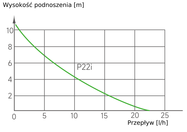
Device diagram
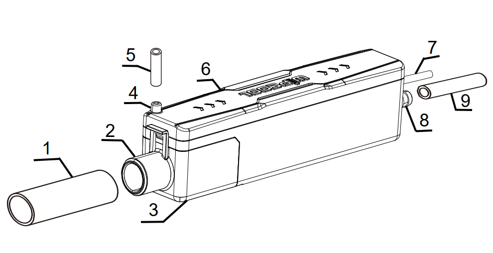
| No. | Name |
|---|---|
| 1 | Inlet pipe |
| 2 | Condensate inlet |
| 3 | Integrated tank with internal filter |
| 4 | Air vent |
| 5 | Vent pipe - internal diameter 6 mm, length 35 mm |
| 6 | Housing |
| 7 | Power and alarm cable |
| 8 | Condensate outlet |
| 9 | Discharge pipe |
Pump dimensions
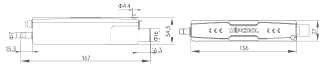
Contents
After unpacking, check that the contents are complete and in good condition. Report any missing or damaged items to the seller.
- ■P22i condensate pump with power and alarm cable - 1 pc.
- ■Vent pipe, length 35 mm, internal diameter 6 mm - 1 pc.
- ■Vacuum breaker for pipe with 6 mm internal diameter - 1 pc.
- ■Inlet pipe - 1 pc.
- ■Cable ties 100 × 3 mm - 2 pcs.
- ■Cable ties 300 × 5 mm - set.
- ■Hook-and-loop tape 25 × 100 mm - 1 pc.
- ■User manual - 1 pc.
Provide the 6 × 9 mm discharge pipe separately.
Transport and storage
Transport
- ■Transport the pump in its original packaging. Secure it against movement during transport.
- ■Do not throw the device. Protect it from shocks, excessive vibration, moisture, dust and extreme temperatures.
Storage
- ■Store the pump horizontally in a dry, well-ventilated place, away from sunlight and heat sources, at a temperature of 5–50 °C.
Application
The pump is designed to drain condensate from split system, ducted and cassette air conditioning units.
Installation
- 01Connect the inlet pipe to the air conditioner's condensate tray drain and run it with a downward slope towards the pump so that condensate flows by gravity.
- 02Connect the other end of the inlet pipe to the condensate inlet and secure it with a cable tie. Connect the vent pipe to the air vent.
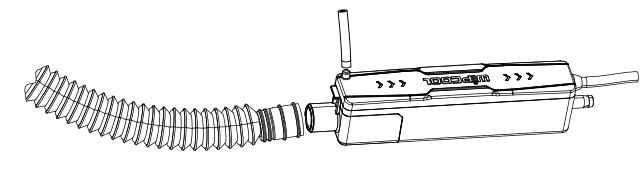
- ■3. Connect the 6 × 9 mm discharge pipe to the condensate outlet and secure it with a cable tie. The head must be less than 10 m.
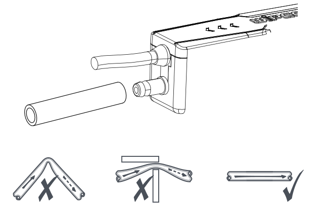
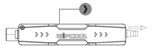
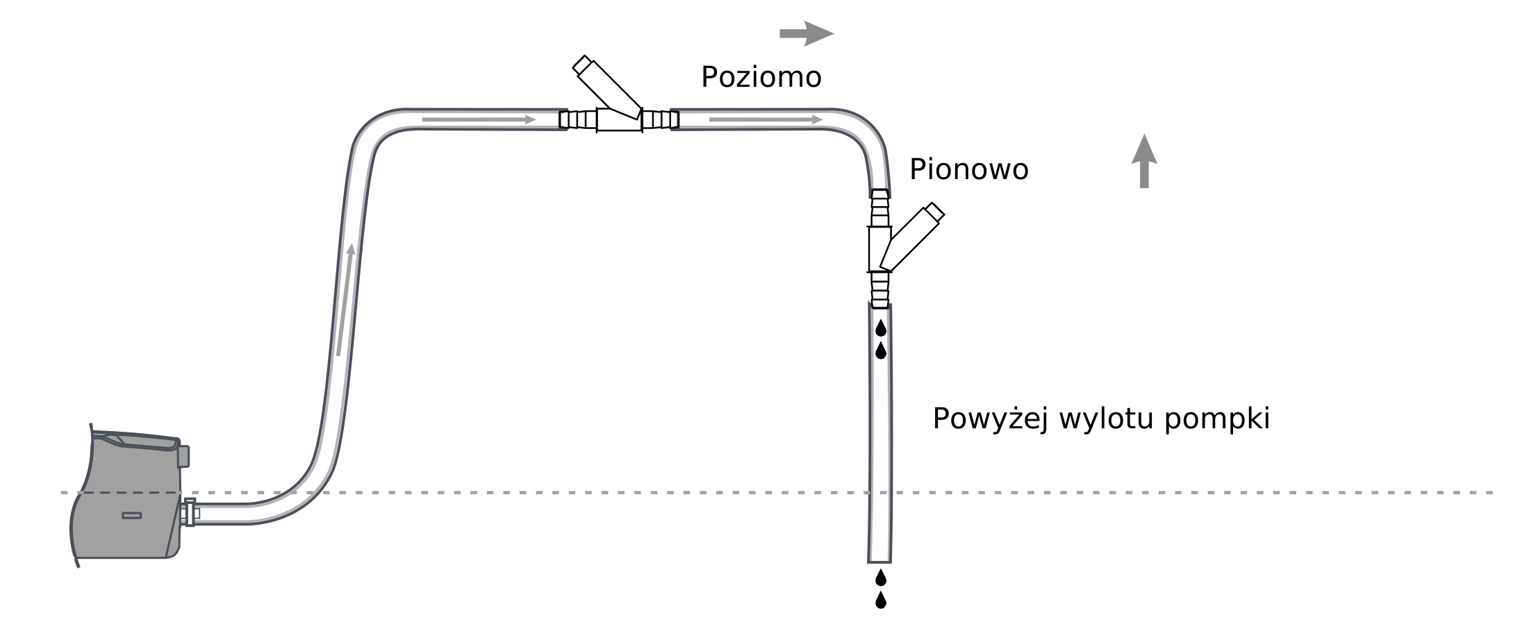
- ■4. Route the discharge pipe without bends, kinks or pinches, following the direction of condensate flow (figures 5–6), and fit the vacuum breaker in the pipe above the condensate outlet, horizontally or vertically (figure 7). The vacuum breaker prevents the column of liquid in the discharge pipe from draining the tank automatically.
- ■5. Secure the pump behind the indoor unit with hook-and-loop tape. Level the pump; the tape reduces vibration transmission.
Connection
Power supply
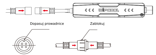
- 01Align the guides on the power and alarm cable connector, insert the connector in the direction of the arrow and lock the nut.
- 02Connect the power and alarm cable to the indoor unit wiring so that the pump's power supply does not switch off with the air conditioner.
| Designation | Function | Conductor colour |
|---|---|---|
| L | Live conductor | Brown |
| N | Neutral conductor | Blue |
| COM | Alarm circuit common contact | Black |
| NC | Alarm circuit normally closed contact | Black |
Alarm circuit
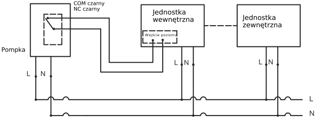
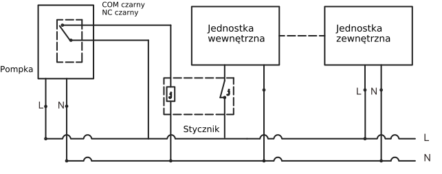
Connect COM and NC to a circuit that stops the air conditioner when the condensate level is high. Select an option compatible with the air conditioner's documentation.
If the air conditioner has a level control input, connect the alarm contacts to it according to its wiring diagram.
If the air conditioner does not have a level control input, use a suitably rated contactor or another alarm device.
Operation
After installing all components, connect the power supply and check that the pump operates correctly.
Maintenance
General guidance
Inspect and clean the pump before and after the cooling season.
- ■Do not use alcohol, petrol, solvents, corrosive substances or strong detergents. Do not allow chemicals to enter the pump.
- ■Disconnect the pump from the power supply when chemically cleaning the air conditioner. Before reconnecting it, thoroughly flush any cleaning agent residue from the air conditioning system.
Cleaning
Remove debris from the pipes, condensate inlet and outlet. After cleaning, connect the power supply and check that the pump operates correctly. Do not clean the inside of the tank or the filter yourself. Have the inside of the tank and the filter cleaned by the service team - submit a service request at wipcool.pl/serwis.
Troubleshooting
| Problem | Possible cause | Solution |
|---|---|---|
| Pump does not operate | No power supply | Check the pump's power supply. |
| Pump does not operate | Incorrect wiring | Check the connections of the L and N power conductors. |
| Pump does not operate | Pump is not level | Level the pump and check the condensate level. |
| Pump does not operate | Incorrect voltage | Check the supply voltage and compare it with the rating plate. |
| Pump runs continuously | Pump is not level | Level the pump. |
| Pump runs continuously | Deposits in the tank | Have the tank cleaned by the service team - submit a service request at wipcool.pl/serwis. |
| Pump runs but does not drain condensate | Blocked condensate inlet or outlet | Check and clean the condensate inlet and outlet. |
| Pump runs but does not drain condensate | Pump is not level | Level the pump. |
| Condensate leaks | Damaged discharge pipe | Check the pipe and replace it if damaged. |
| Condensate leaks | Incorrect pipe connection | Check the connection and secure it with a cable tie. |
| Noisy pump operation | Damaged internal components | Have the pump repaired by the service team - submit a service request at wipcool.pl/serwis. |
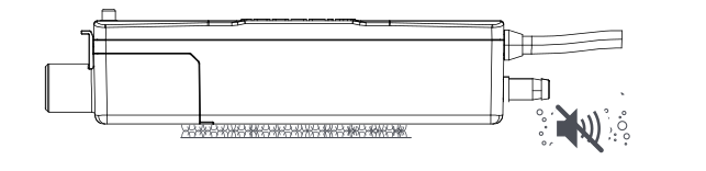
| Pump gurgles or makes noise after switching off | The end of the discharge pipe is lower than the pump, and the vacuum breaker is not fitted or is below the condensate outlet, causing siphoning | Fit the vacuum breaker above the condensate outlet (figure 7) or route the pipe so that its end is higher than the pump. |
| Pump switches on and off too frequently | Excessive condensate inflow | Check that the condensate inflow does not exceed the pump's maximum flow rate (22 l/h). |
| Pump switches on and off too frequently | Pump is not level | Level the pump. |
| Alarm activates | Condensate level too high | Check that the inlet is clear and that condensate drains properly. |
| Alarm activates | Incorrect alarm connection | Check the connections of the COM and NC alarm contact conductors. |
Waste electrical and electronic equipment
- 01The crossed-out bin symbol means that the device must not be disposed of with other waste at the end of its life.
Under applicable regulations on waste electrical and electronic equipment, products marked with the separate collection symbol must not be placed with other municipal waste. Because they contain hazardous substances, electronic products that are not collected separately may be dangerous to the environment and human health. Proper separate collection of waste electrical and electronic equipment prevents adverse effects on the environment.
By taking waste equipment to a collection point, the user contributes to its reuse, recycling and recovery.
Recycling - a method of protecting the environment. The process of recovering substances from waste that can be reused as raw materials.
Waste recovery - the use of waste that has lost its useful value, such as plastics, paper and cardboard, as secondary raw materials (colloquially also its destruction).
Information on the waste electrical and electronic equipment collection system
- ■Waste electrical and electronic equipment must not be placed with other waste.
- ■The collection of incomplete electrical and electronic equipment and parts from waste equipment is prohibited.
- ■A distributor delivering equipment intended for households to a purchaser must collect waste household equipment free of charge at the place of delivery, provided that the waste equipment is of the same type and performs the same function as the equipment delivered.
- ■The user may hand over waste equipment to a waste equipment collector, a treatment facility or a municipal waste collector in the municipality.
- ■Information on collection points is available on the Public Information Bulletin (BIP) websites of regional, city and municipal authorities.
Service and documents
Before submitting a service request, prepare:
- ■Model - found on the device's rating plate and on the invoice.
- ■Serial number - if there is none, provide the production number (e.g. 11/2025), usually found on the underside of the device.
- ■Proof of purchase - an invoice or receipt from an authorised distributor.
- ■Description of the fault - what is happening, when it started and under what conditions.
You can submit a service request at wipcool.pl/serwis. You will also find the warranty terms there.