
 Distribution PL · 4REF
Wipcool PWM-40 user manual
Read the entire manual before first use. Keep it for as long as you use the device.
Wipcool PWM-40 user manual
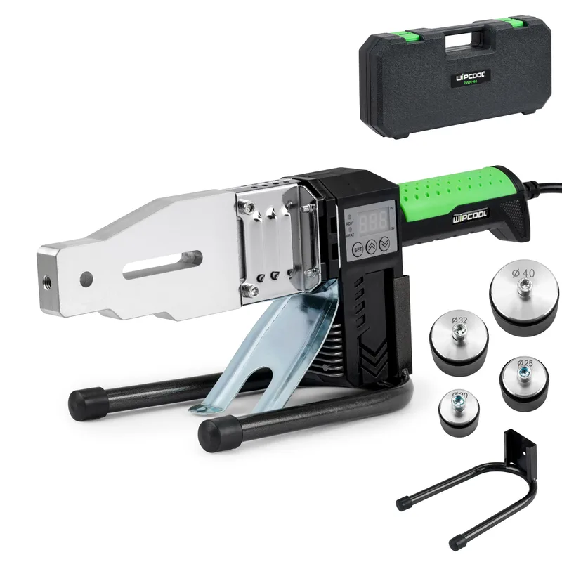
The Wipcool PWM-40 socket fusion welder is used to join PP-R, PE and PP-C pipes and fittings. It has electronic temperature control and a digital display.
The user manual is an integral part of the product. Please read this manual carefully and follow all instructions strictly.
General information
Wipcool products are designed for professional use by qualified air conditioning and refrigeration engineers. As the manufacturer, Wipcool stipulates that our equipment should only be operated by suitably qualified and trained personnel.
- ■Observe all local safety regulations and general safety standards when using the Wipcool PWM-40 socket fusion welder.
- ■The user manual should be kept near the device so that personnel can access it easily at all times.
- ■Before use, qualified personnel should read the user manual carefully and understand all the instructions it contains.
- ■The manufacturer accepts no liability for any damage resulting from improper use, failure to follow the user manual, lack of personnel qualifications or any unauthorised modifications to the device.
- ■The general terms of sale contained in the sales documents apply.
Symbols and conventions
Symbols and markings used on the device and in the manual:
- 01
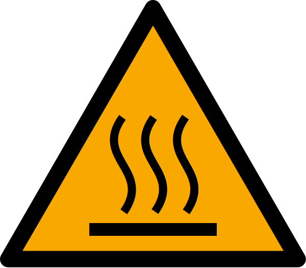 Hot surface - allow to cool before touching.
- 02
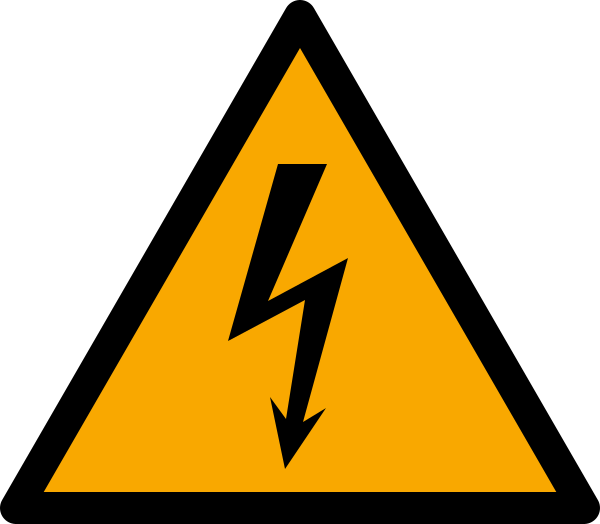 Hazardous voltage - risk of electric shock.
- 03
 Notice - risk of damage to the device or an incorrect result.
- 04
 Indicates that the product meets the health, safety and environmental standards applicable in the European Union.
- 05
 Do not dispose of the welder with household waste.
Safety information
- ■Regularly check the condition of the welder, accessories, power cable and plug. Do not connect or use the device if you notice any damage.
- ■Do not weld materials other than PP-R, PE and PP-C.
- ■Use only original accessories and heating dies intended for this model.
- ■Do not use the welder in potentially explosive areas or in the presence of flammable materials.
- ■Do not use the welder outdoors in the rain. Protect the interior of the device from water and other liquids.
Technical specifications
Device diagram
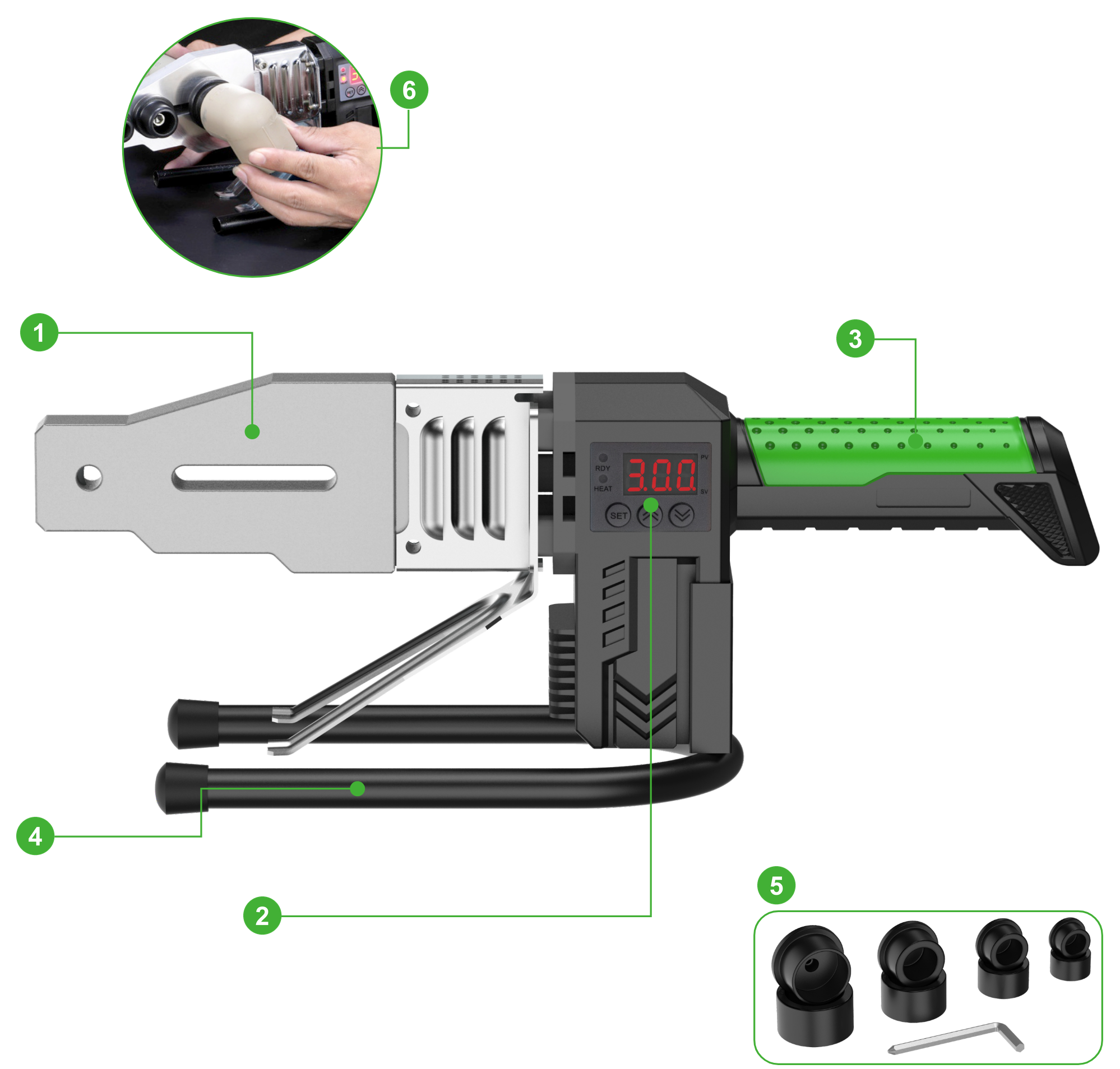
Welder components:
- 01Heating plate.
- 02Display and control buttons.
- 03Handle.
- 04Stand.
- 05Heating sockets.
- 06Close-up of fusion welding (welder in operation).
Package contents
- ■PWM-40 welder with stand.
- ■Heating dies for pipes of 20 / 25 / 32 / 40 mm diameter.
- ■Hex key.
- ■Tool case.
- ■User manual.
Transport and storage
Do not throw the welder during transport. Protect it from shocks, excessive vibration, moisture, dust and extreme temperatures.
Store the welder horizontally in a dry, well-ventilated place, away from direct sunlight and heat sources.
Assembly
- 01Place the welder on the stand, seating the handle in both sockets on the stand. Hold the stand down with your foot during use.
- 02Select heating dies to match the pipe diameter and secure them to the heating plate with M8 × 45 hex socket screws. Tighten the screws with the hex key.
Connection
Insert the power cable plug into an earthed 230 V~ socket.
How to use
Setting the temperature and heating
The red indicator shows that the device is heating, and the green indicator shows that it has reached the set temperature.
- 01Keep the factory setting or change it using the ▲ (increase) and ▼ (decrease) buttons. A short press changes the setting once, while holding the button changes it continuously. Press SET to confirm the setting.
- 02After confirming the setting, wait 3–5 s for heating to start.
- 03Wait until the red indicator goes out and the green indicator comes on.
- 04Wait until the red indicator comes on again. This indicates that the device has switched to maintaining the set temperature. Welding can begin from this point. Preparation for use usually takes less than 10 min.
Welding pipes and fittings
- 01Cut the pipe square using a pipe cutter.
- 02Push the pipe and fitting onto the heating dies at the same time, without turning them. Follow the insertion depth and heating time given in the table.
- 03Quickly remove the heated parts from the heating dies and join the pipe to the fitting. Do not push them together with excessive force, as this may bend the end of the pipe. Follow the joining and cooling times given in the table.
| Outside diameter [mm] | Insertion depth [mm] | Heating time [s] | Joining time [s] | Cooling time [min] |
|---|---|---|---|---|
| 20 | 14 | 5 | 4 | 3 |
| 25 | 16 | 7 | 4 | 3 |
| 32 | 18.1 | 8 | 4 | 4 |
| 40 | 20.5 | 12 | 6 | 4 |
If the ambient temperature during use is below 5 °C, increase the heating time by 50%.
Finishing work
When you have finished, remove the plug from the socket. Put the welder in the case only after it has cooled completely.
Maintenance
Disconnect the welder from the power supply before maintenance or servicing.
- 01Clean the housing with a soft, dry or slightly damp cloth. Do not use alcohol, petrol, solvents, corrosive substances or strong detergents. Do not immerse the device in water or other liquids.
- 02After the device has cooled, remove plastic residue from the heating dies with a soft cloth or wooden tool. Do not use metal tools: a damaged Teflon coating causes plastic to stick, reduces joint quality and shortens the service life of the heating dies.
- 03Replace damaged or worn heating dies. Check that the stand is stable and the heating dies are secure.
If the power cable is damaged, do not replace it yourself. Have it repaired by the service centre - submit a request at wipcool.pl/serwis.
Troubleshooting
| Problem | Possible cause | Solution |
|---|---|---|
| The welder does not work when connected to the power supply | No power supply | Check the mains connection and power socket. |
| The welder does not work when connected to the power supply | Damaged cable or plug | Have it repaired by the service centre - submit a request at wipcool.pl/serwis. |
| The welder does not heat up | Incorrect temperature setting | Check the temperature setting. |
| The welder does not heat up | Damaged heating element | Have it repaired by the service centre - submit a request at wipcool.pl/serwis. |
| The temperature is unstable | Dirty or damaged heating dies | Clean the heating dies (see ‘MAINTENANCE’) or replace them (for fitting, see ‘ASSEMBLY’). |
| The temperature is unstable | Incorrect supply voltage | Check the power supply specifications. |
| Plastic sticks to the heating dies | Damaged Teflon coating | Replace the heating dies (for fitting, see ‘ASSEMBLY’). |
| Plastic sticks to the heating dies | Operating temperature too high | Reduce the temperature. |
| Pipe joints leak | Incorrect heating time | Repeat the welding, following the heating time given in the table in ‘HOW TO USE’. |
| Pipe joints leak | Welding temperature too low | Increase the temperature. |
| The display does not work correctly | Power supply or electronics problem | Remove the plug from the socket, then plug it in again. |
| The device switches off during use | Thermal protection has tripped | Remove the plug from the socket. Once the welder has cooled, plug it in again. |
Waste electrical and electronic equipment
- 01The crossed-out bin symbol means that the device must not be disposed of with other waste at the end of its life.
Under the applicable regulations on waste electrical and electronic equipment, products marked with the separate collection symbol must not be placed with other municipal waste. Because they contain harmful substances, electronic products that are not sorted separately may be hazardous to the environment and human health. Proper separate collection of waste electrical and electronic equipment prevents adverse effects on the environment.
By taking waste equipment to a collection point, the user contributes to its reuse, recycling and recovery.
Recycling - a method of protecting the environment. The process of recovering substances from waste that can be reused as raw materials.
Waste recovery - the use of waste that has lost its useful value, such as plastics, paper and cardboard, as secondary raw materials; the term also commonly refers to its destruction.
Information on the collection system for waste electrical and electronic equipment
- ■Waste electrical and electronic equipment must not be placed with other waste.
- ■The collection of incomplete electrical and electronic equipment and parts from waste equipment is prohibited.
- ■A distributor delivering equipment intended for households to a purchaser must collect waste household equipment free of charge at the place of delivery, provided that the waste equipment is of the same type and performs the same function as the equipment delivered.
- ■The user may hand over waste equipment to a waste equipment collector, a treatment facility or a municipal waste collector in the local authority area.
- ■Information on collection points is available on the Public Information Bulletin (BIP) websites of regional, city and municipal offices.
Service and documents
Before submitting a request, prepare:
- ■Model - shown on the device nameplate and invoice.
- ■Serial number - if there is none, provide the production number (e.g. 11/2025), usually found on the bottom of the device.
- ■Proof of purchase - an invoice or receipt from an authorised distributor.
- ■Description of the fault - what is happening, when it started and under what conditions.
You can submit a service request at wipcool.pl/serwis. The warranty terms are also available there.