
 Distribution PL · 4REF
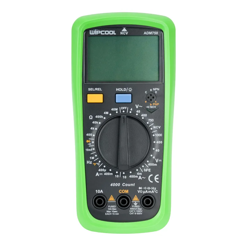
Wipcool ADM750 user manual
Read the entire manual before first use. Keep it for as long as you use the device.
Wipcool ADM750 user manual
The Wipcool ADM750 Digital Multimeter measures voltage, current, resistance, capacitance, frequency and temperature. It also performs continuity and diode tests, transistor hFE measurements and non-contact AC voltage detection (NCV).
The user manual is an integral part of the product. Please read this manual carefully and follow all instructions strictly.
General information
Wipcool products are designed for professional use by qualified air conditioning and refrigeration engineers. As the manufacturer, Wipcool stipulates that our equipment should be operated only by suitably qualified and trained personnel.
- ■Follow all local safety regulations and general safety standards when using the Wipcool ADM750 Multimeter.
- ■Keep the user manual near the device so that personnel can access it easily at all times.
- ■Before use, qualified personnel should read the user manual carefully and understand all instructions it contains.
- ■The manufacturer accepts no liability for any damage resulting from improper use, failure to follow the user manual, insufficiently qualified personnel or any unauthorised modifications to the device.
- ■The general terms of sale contained in the sales documents apply.
Symbols and conventions
Symbols and markings used on the device and in the manual:
- 01
 Low battery - replace the batteries.
- 02
 Earth.
- 03
 Double insulation.
- 04
 AC - alternating current or voltage.
- 05
 DC - direct current or voltage.
- 06
 Hazardous voltage - risk of electric shock.
- 07
 Warning - read the text in the box next to the symbol.
- 08
 Notice - risk of damage to the device or an incorrect result.
- 09
 Indicates that the product meets the health, safety and environmental standards applicable in the European Union.
- 10
 Do not dispose of the meter with household waste.
The CAT II 1000 V / CAT III 600 V markings specify the measurement category and rated voltage of the meter. COM denotes the common measurement socket, OFF denotes the off position, and OL denotes an exceeded range or an open circuit, depending on the function.
Safety information
The design complies with IEC 61010-1:2010, IEC 61010-2-030:2010, IEC 61010-2-033:2012, IEC 61326-1:2013 and IEC 61326-2-2:2013.
- ■Set the correct function and range before connecting the probes. Do not turn the dial during measurement.
- ■Do not exceed the permitted measurement values shown at the sockets and in the technical specifications.
- ■Do not modify the meter's internal circuitry.
- ■Do not use or store the meter at high temperatures or humidity. Observe the environmental conditions specified in the technical specifications.
Technical specifications
Accuracy is specified as ±(a% of reading + b counts in the least significant digit). Reference conditions: 18–28 °C (fluctuations up to ±1 °C), relative humidity ≤75%. Outside this range, the temperature coefficient is 0.1 × the specified accuracy per °C.
For an RF field ≤1 V/m, add 5% of the range to the specified accuracy. At RF >1 V/m, accuracy is not specified.
Direct voltage (DC)
| Range | Resolution | Accuracy |
|---|---|---|
| 400.0 mV | 0.1 mV | ±(0.5% + 5) |
| 4.000 V | 0.001 V | ±(0.5% + 5) |
| 40.00 V | 0.01 V | ±(0.5% + 5) |
| 400.0 V | 0.1 V | ±(0.5% + 5) |
| 1000 V | 1 V | ±(0.7% + 3) |
Input impedance: approximately 10 MΩ. With an open input, the mV reading may be unstable; once a voltage source is connected, it stabilises to within ±3 counts in the least significant digit. Maximum input voltage: ±1000 V. OL at a voltage ≥1010 V.
Alternating voltage (AC)
| Range | Resolution | Accuracy |
|---|---|---|
| 4.000 V | 0.001 V | ±(1.0% + 2) |
| 40.00 V | 0.01 V | ±(0.8% + 3) |
| 400.0 V | 0.1 V | ±(0.8% + 3) |
| 750 V | 1 V | ±(0.8% + 3) |
Input impedance: approximately 10 MΩ. Bandwidth: 40–400 Hz. The meter measures the average value and displays it as the RMS value of a sine wave. Maximum input voltage: 750 V AC. OL at a voltage ≥760 V.
Resistance
| Range | Resolution | Accuracy |
|---|---|---|
| 400.0 Ω | 0.1 Ω | ±(1.0% + 2) |
| 4.000 kΩ | 0.001 kΩ | ±(0.8% + 2) |
| 40.00 kΩ | 0.01 kΩ | ±(0.8% + 2) |
| 400.0 kΩ | 0.1 kΩ | ±(0.8% + 2) |
| 4.000 MΩ | 0.001 MΩ | ±(1.0% + 2) |
| 40.00 MΩ | 0.01 MΩ | ±(1.2% + 3) |
Continuity and diodes
| Function | Resolution | Indication |
|---|---|---|
| Continuity | 0.1 Ω | R ≤10 Ω: continuous signal |
| Diode | 0.001 V | Open-circuit voltage approximately 4 V; test current approximately 1.4 mA |
Capacitance
| Range | Resolution | Accuracy |
|---|---|---|
| 4.000 nF | 0.001 nF | REL: ±(4% + 10) |
| 40.00 nF | 0.01 nF | REL: ±(4% + 10) |
| 400.0 nF | 0.1 nF | ±(4% + 10) |
| 4.000 µF | 0.001 µF | ±(4% + 5) |
| 40.00 µF | 0.01 µF | ±(4% + 5) |
| 400.0 µF | 0.1 µF | ±(4% + 5) |
| 10.00 mF | 0.01 mF | ±10% |
The response time for capacitance measurements ≤10 mF is up to 6 s.
Temperature
| Range | Resolution | Accuracy |
|---|---|---|
| -40–+40 °C | 1 °C | ±4 °C |
| >40–500 °C | 1 °C | ±(1.0% + 3) |
| >500–1000 °C | 1 °C | ±(2.0% + 2.5) |
Direct current (DC)
| Range | Resolution | Accuracy |
|---|---|---|
| 400.0 µA | 0.1 µA | ±(0.8% + 3) |
| 400.0 mA | 0.1 mA | ±(0.8% + 3) |
| 10.00 A | 0.01 A | ±(1.2% + 5) |
Continuous alarm signal at current ≥10 A; OL at current >10.10 A.
Alternating current (AC)
| Range | Resolution | Accuracy |
|---|---|---|
| 4.000 mA | 0.001 mA | ±(1.0% + 2) |
| 40.00 mA | 0.01 mA | ±(1.0% + 2) |
| 400.0 mA | 0.1 mA | ±(1.0% + 2) |
| 10.00 A | 0.01 A | ±(1.5% + 3) |
Bandwidth: 40–400 Hz. RMS reading; accuracy applies to 5–100% of the range. With the probes shorted, the permitted residual reading is less than 2 counts in the least significant digit. Alarm and OL thresholds are the same as for DC current.
Frequency
| Range | Resolution | Accuracy |
|---|---|---|
| 10.00 Hz–1.000 MHz | 0.01 Hz–1 kHz | ±(0.1% + 4) |
For frequencies ≤100 kHz, input amplitude: 200 mV RMS–30 V RMS; for >100 kHz–1 MHz: 600 mV RMS–30 V RMS.
Overload protection is 1000 V RMS AC/DC for voltage, resistance, continuity, diodes, capacitance, temperature and frequency, and 250 V RMS for current inputs. Protection ratings do not increase the measurement ranges or the permitted input amplitude.
Device diagram
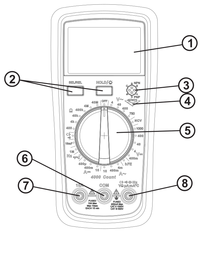
| No. | Name |
|---|---|
| 1 | LCD display |
| 2 | Function buttons |
| 3 | PNP/NPN transistor socket |
| 4 | Alarm indicator |
| 5 | Function and range selector dial |
| 6 | COM socket |
| 7 | 10 A current socket |
| 8 | VΩmA socket |
Connect the black lead to COM. Connect the red lead to VΩmA for voltage, resistance, capacitance, frequency, diode and continuity measurements, and current measurements up to 400 mA. Use the separate 10 A socket for the 10 A range.
Buttons
| Button | Operation |
|---|---|
| SEL/REL | Selects the diode or continuity test and the temperature unit. Zeros the baseline value when measuring voltage, current, capacitance and resistance on the 400 Ω range (REL - relative measurement). |
| HOLD - hold reading | Briefly press HOLD to hold the reading on the display. Press it briefly again to resume measurement. H in the top left corner of the LCD indicates that the reading is held. |
| HOLD - hold for ≥2 s | Turns the backlight on or off. The backlight switches off automatically after 30 s. |
Package contents
After unpacking, check that the set is complete and in good condition. Report any missing or damaged items to the seller.
| Item | Quantity |
|---|---|
| ADM750 Multimeter | 1 |
| Test leads | 1 pair |
| User manual | 1 |
Transport and storage
- ■Transport the meter in its original packaging.
- ■Store the meter in a dry place, away from direct sunlight and heat sources, at a temperature of -10–+50 °C.
How to use
Getting started
Before first use, insert the batteries as described in ‘Replacing the batteries’ (MAINTENANCE section). Switch on the meter by turning the function and range selector dial from OFF to the desired function. The meter is ready to measure after approximately 2 s. The ‘-’ sign indicates negative polarity.
Automatic power-off
- ■The meter switches off automatically after 15 min of inactivity. Press any button to resume operation; you will hear a single beep.
- ■To disable automatic power-off, hold SEL/REL and switch on the meter by turning the dial from OFF to the desired function.
Audible signals and low battery
- ■A signal lasting approximately 0.25 s sounds when a button is pressed or the dial is turned. You will hear 5 beeps approximately one minute before automatic power-off and one long beep during power-off.
- ■At an input voltage ≥1000 V AC or DC, the buzzer sounds continuously. For AC measurements, the alarm does not sound between 750 V and 1000 V - it therefore does not warn you when the permitted 750 V is exceeded.
- ■When the battery voltage falls below 2.5 V, the low battery indicator appears in the bottom left corner of the LCD and flashes for 3 s every 3 s; the meter continues to measure. Replace the batteries to prevent incorrect readings. Below 2.2 V, the meter displays only this indicator and does not take measurements.
Measuring AC/DC voltage
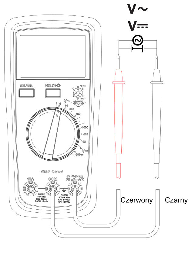
- 01Set the dial to V DC or V AC according to the type of voltage. If the value is unknown, start with the highest range.
- 02Connect the black lead to COM and the red lead to VΩmA. Place the probes on the points between which you are measuring voltage.
- 03Read the voltage. If necessary, gradually reduce the range, removing the probes before each change and reapplying them afterwards, until you obtain an accurate reading. If OL appears, remove the probes and increase the range within the permitted input value.
High impedance in the circuit under test may reduce measurement accuracy.
Measuring resistance
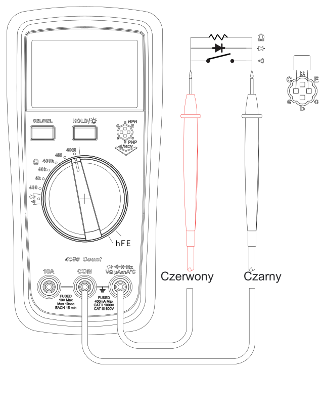
- 01Set the dial to Ω. Connect the black lead to COM and the red lead to VΩmA.
- 02Short the probes together. If the reading is greater than 0.5 Ω, check whether the leads are loose or damaged. On the 400 Ω range, press SEL/REL to zero the lead resistance.
- 03Place the probes across the resistor and read the result. For high resistance, wait a few seconds for the reading to stabilise.
OL indicates an open circuit or an exceeded range. The leads may introduce an error of 0.1–0.2 Ω. If you are not using REL, subtract the resistance of the shorted leads from the result.
Continuity test
- 01With the circuit switched off and discharged, set the dial to the continuity and diode test position. Press SEL/REL to select continuity.
- 02Connect the black lead to COM and the red lead to VΩmA. Place the probes at the ends of the section under test, as shown in figure 3.
- 03At a resistance ≤10 Ω, you will hear a continuous signal and the alarm indicator will light up (no. 4 in figure 1).
Diode test
- 01With the circuit switched off and discharged, set the dial to the continuity and diode test position. Press SEL/REL to select the diode test.
- 02Connect the black lead to COM and the red lead to VΩmA. Place the red probe on the anode and the black probe on the cathode, as shown in figure 3.
- 03Read the voltage drop. For a silicon diode, a typical reading is 0.5–0.8 V. OL indicates an open circuit or reversed polarity.
Measuring transistor hFE
Measure the transistor with it disconnected from the circuit.
- 01Set the dial to hFE. Select the PNP or NPN socket according to the transistor type.
- 02Insert the B (base), E (emitter) and C (collector) leads into the corresponding holes in the socket shown in figure 3. Read the hFE value from the display.
Measuring capacitance
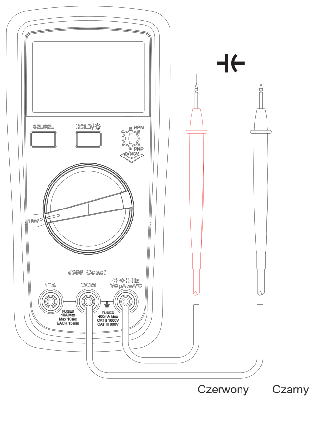
- 01Set the dial to capacitance. Connect the black lead to COM and the red lead to VΩmA.
- 02With the probes open, read the baseline value resulting from the meter's internal capacitance. For capacitance ≤200 nF, press SEL/REL so that the meter subtracts it automatically (REL mode); this also applies to readings on the 400 nF range.
- 03Place the probes on the capacitor terminals. For high capacitance, wait a few seconds for the reading to stabilise and read the result.
Without REL, subtract the value indicated with the probes open from the result. OL may indicate a shorted capacitor or an exceeded range.
Measuring frequency
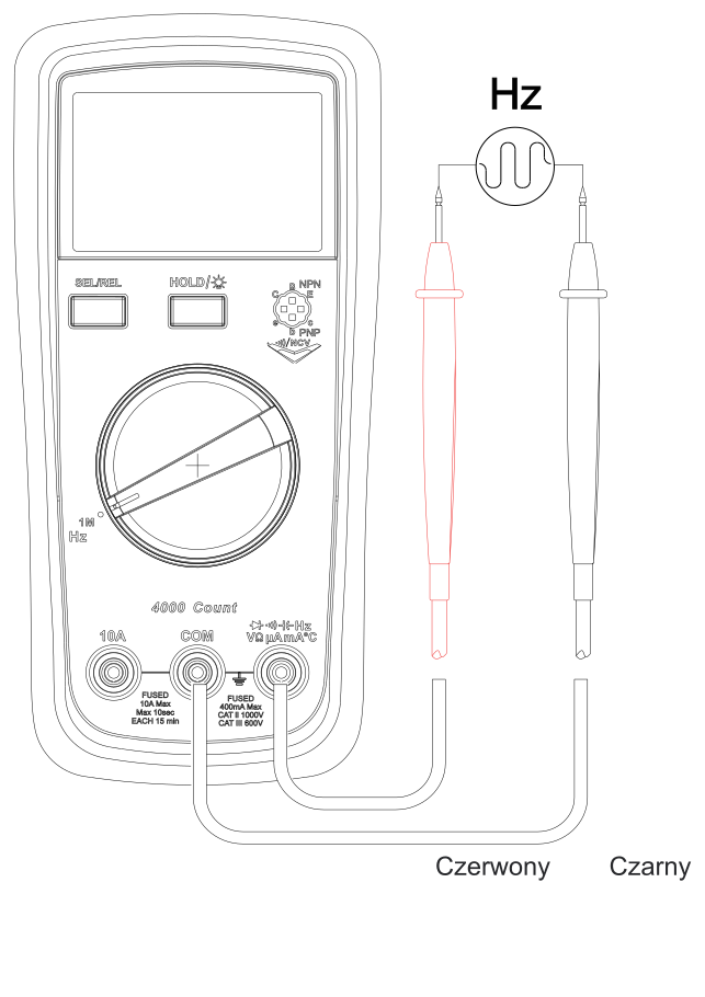
- 01Set the dial to Hz. Connect the black lead to COM and the red lead to VΩmA.
- 02Place the probes on two points of the signal source and read the frequency.
When no signal is connected, the mains field may cause a reading of approximately 50 Hz. This does not affect the measurement accuracy of a connected signal.
Measuring AC/DC current
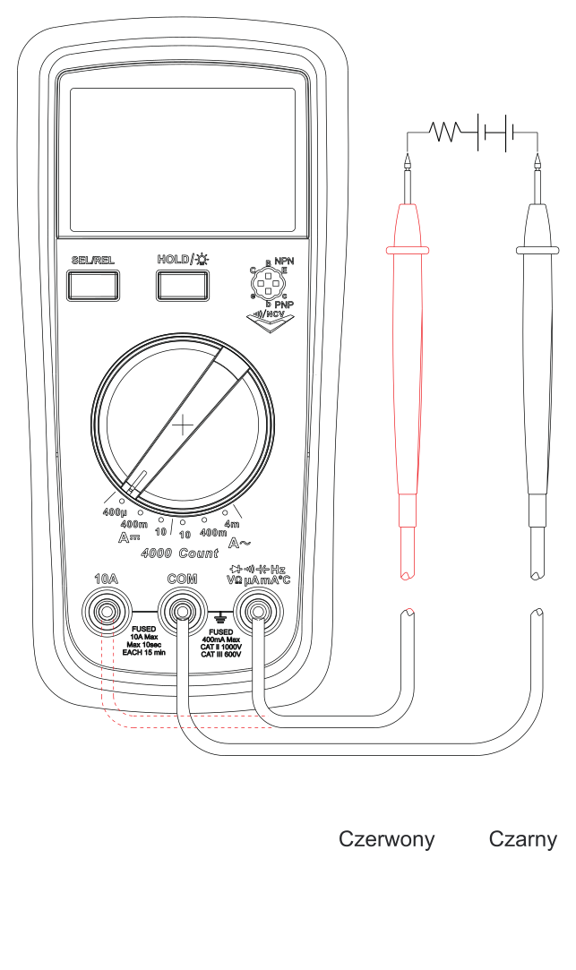
- 01Set the dial to the appropriate DC or AC current range. If the current is unknown, select the highest range and the 10 A socket.
- 02Connect the black lead to COM and the red lead to VΩmA for ranges up to 400 mA or to 10 A for the 10 A range. Check the sockets and dial position.
- 03With the circuit switched off, connect the meter in series. Switch on the power to the circuit under test in accordance with its instructions and read the current.
- 04Before disconnecting the meter, switch off the circuit under test again, set the meter to OFF and disconnect the leads.
If you start with the highest current range, reduce it gradually. Before each change of range or socket, switch off the circuit under test and disconnect the meter. An overload may blow the fuse for the corresponding input. Stop measuring if the alarm sounds or OL appears.
Measuring temperature
A type K thermocouple is required for measurement.
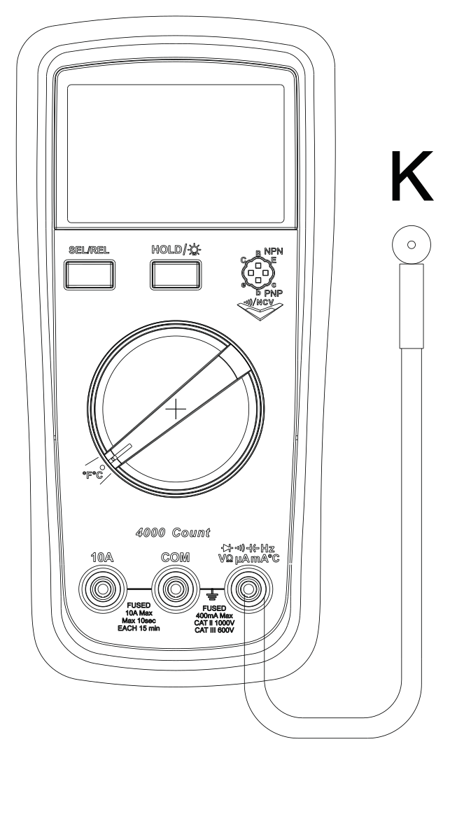
- 01Set the dial to temperature and press SEL/REL to select °C.
- 02Connect the type K thermocouple to the COM and VΩmA sockets (marked ‘-’ and ‘+’ respectively for temperature measurement), observing the polarity. Place the probe on the object under test.
- 03Wait for the reading to stabilise and read the temperature.
OL appears on the display when no thermocouple is connected.
Non-contact voltage detection - NCV
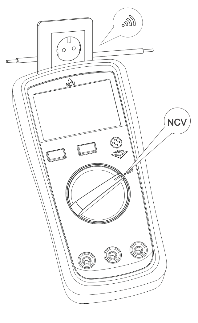
NCV mode detects the presence of alternating voltage or an electromagnetic field.
- 01Set the dial to NCV and bring the front of the meter close to the object under test.
- 02Watch the display and alarm indicator and listen to the buzzer. The meter indicates the field with up to four ‘-’ segments. A stronger indication is shown by more segments, more frequent beeps and faster flashing of the alarm indicator.
Completing the measurement
Complete the current measurement according to step 4 in ‘AC/DC current measurement’.
For the other functions, move the probes or thermocouple away from the object under test; when measuring hFE, remove the transistor from the socket, and in NCV mode, move the meter away. Set the dial to OFF and remove the leads from the meter sockets.
Maintenance
General recommendations
- ■Clean the housing with a soft, damp cloth and mild detergent. Do not use abrasives or solvents.
- ■If the meter does not work correctly, stop using it. Have it repaired by the service department - submit a service request at wipcool.pl/serwis.
Replacing the batteries
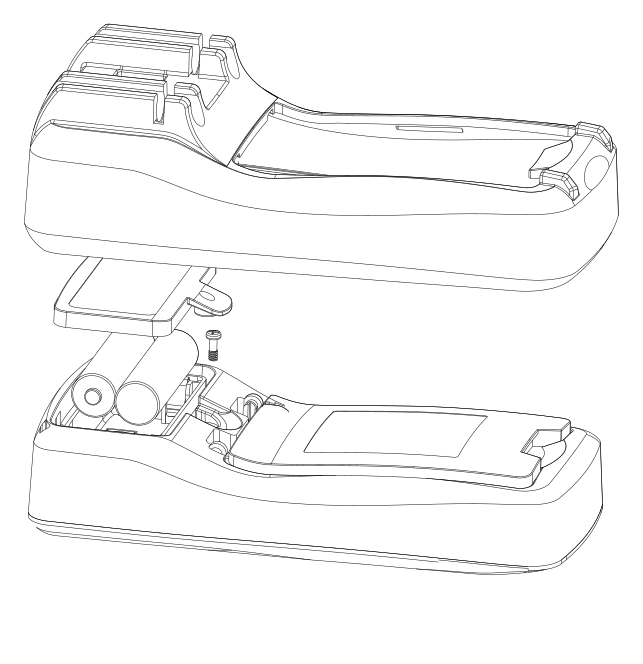
- 01Remove the protective cover.
- 02Undo the battery compartment cover screw and remove the cover.
- 03Remove the used batteries. Insert two new AA 1.5 V batteries according to the polarity markings.
- 04Fit the battery compartment cover and tighten the screw. Fit the protective cover.
Fuses
A blown fuse may cause some functions to work incorrectly. The replacement fuse must have the same specification. Have it repaired by the service department - submit a service request at wipcool.pl/serwis.
| Designation / input | Specification |
|---|---|
| F1 - µA/mA | Fast-acting, ceramic, 500 mA H 250 V, Ø5 × 20 mm |
| F2 - 10 A | Fast-acting, ceramic, 10 A H 250 V, Ø5 × 20 mm |
Waste electrical and electronic equipment
- 01The crossed-out wheeled bin symbol means that the used device must not be disposed of with other waste.
Under applicable regulations on waste electrical and electronic equipment, products marked with the separate collection symbol must not be disposed of with other municipal waste. Because they contain harmful substances, electronic products that are not sorted separately can be hazardous to the environment and human health. Proper separate collection of waste electrical and electronic equipment prevents adverse effects on the environment.
By taking used equipment to a collection point, you contribute to its reuse, recycling and recovery.
Recycling - one method of protecting the environment. The process of recovering substances from waste that can be reused as raw materials.
Waste recovery - the use of waste that has lost its practical value, such as plastics, paper and cardboard, as secondary raw materials (the term is also commonly used to mean destruction of waste).
Information on the collection system for waste electrical and electronic equipment
- ■Waste electrical and electronic equipment must not be disposed of with other waste.
- ■The collection of incomplete electrical and electronic equipment and parts from waste equipment is prohibited.
- ■A distributor delivering equipment intended for households to a purchaser is required to collect waste household equipment free of charge at the place of delivery, provided that the waste equipment is of the same type and performs the same function as the equipment delivered.
- ■You can hand over waste equipment to a waste equipment collector, a treatment facility or a municipal waste collector in your municipality.
- ■Information on collection points is available on the Public Information Bulletin (BIP) websites of regional, city and municipal offices.
Service and documents
Before submitting a service request, prepare:
- ■Model - shown on the device rating plate and on the invoice.
- ■Serial number - if there is no serial number, provide the production number (e.g. 11/2025), usually found on the underside of the device.
- ■Proof of purchase - an invoice or receipt from an authorised distributor.
- ■Description of the fault - what is happening, when it started and under what conditions.
You can submit a service request at wipcool.pl/serwis. You will also find the warranty terms there.
Warranty period: 1 year.