
 Distribution PL · 4REF
Wipcool CT370 user manual
Read the entire manual before first use. Keep it for as long as you use the device.
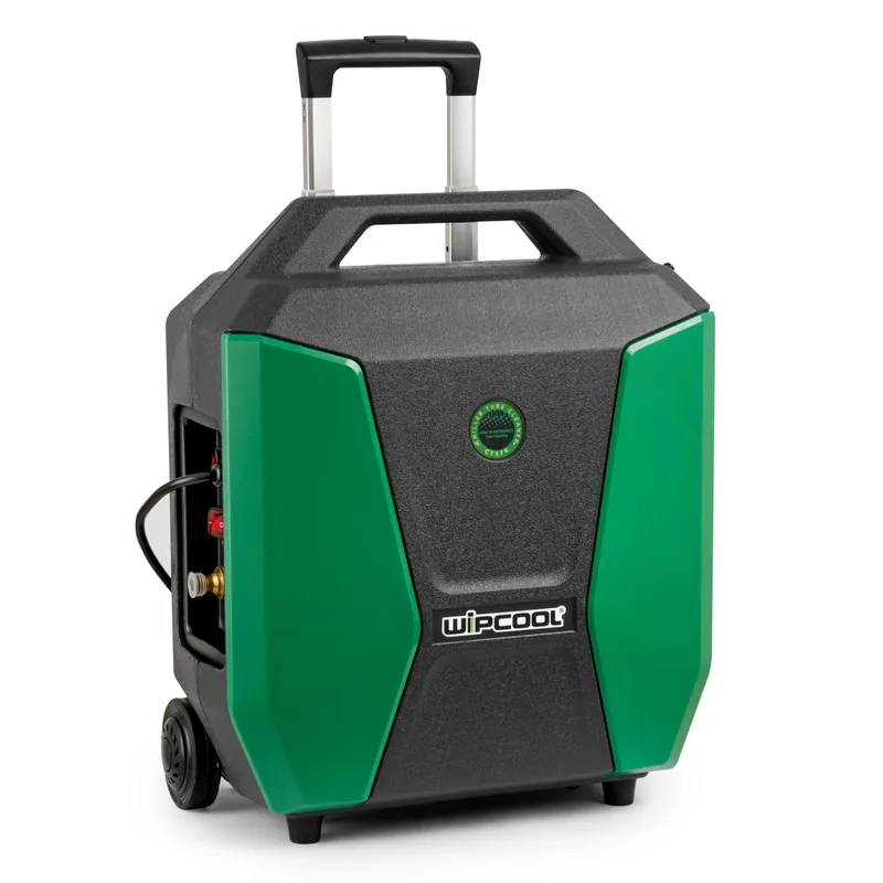
Wipcool CT370 user manual
The Wipcool CT370 is used for mechanical cleaning of heat exchanger tubes in refrigeration and air conditioning systems. A flexible shaft with a brush removes deposits from inside the tubes.
The user manual is an integral part of the product. Please read this manual carefully and follow all instructions strictly.
General information
Wipcool products are designed for professional use by qualified air conditioning and refrigeration engineers. As the manufacturer, Wipcool stipulates that our equipment should be operated only by suitably qualified and trained persons.
- ■Observe all local safety regulations and general safety standards when using the Wipcool CT370 heat exchanger tube cleaner.
- ■The user manual should be kept near the device so that personnel can access it easily at all times.
- ■Before use, qualified personnel should read the user manual carefully and understand all the instructions it contains.
- ■The manufacturer accepts no liability for any damage resulting from improper use, failure to follow the user manual, lack of personnel qualifications or any unauthorised modifications to the device.
- ■The general terms of sale contained in the sales documents apply.
Symbols and conventions
Signs and markings used on the device and in the manual:
- 01
 Warning - read the text in the box next to the symbol.
- 02
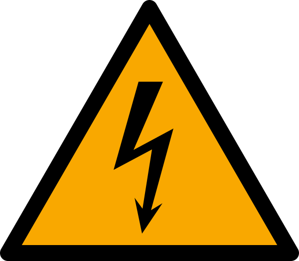 Dangerous voltage - risk of electric shock.
- 03
 Warning of flammable materials.
- 04
 Before starting work, read all safety and installation instructions carefully.
- 05
 Indicates that the product meets the health, safety and environmental standards applicable in the European Union.
- 06RoHSThe product meets the requirements for restricting the use of hazardous substances.
- 07
 Do not dispose of the device with household waste.
Safety information
Work area and operator
- ■Keep the work area clean and well lit. Keep children, bystanders and animals away from the work area.
- ■Do not work when tired or under the influence of alcohol, drugs or medication that impairs your ability to work.
- ■Maintain firm footing and balance, especially on uneven ground; do not overreach.
- ■Wear safety glasses. Select other protective equipment according to the hazards in the work area.
- ■Do not leave the device running unattended. Disconnect the power supply before leaving the work area.
Moving parts
- ■Use only accessories recommended for the CT370.
- ■Before each use, check the condition and attachment of the shaft, brushes and cables, and check the connections for leaks. Check that moving parts are not jammed, damaged or misaligned.
- ■Do not operate the device if it is incomplete or damaged. If the foot switch does not start or stop the drive, stop using the device.
Electrical supply
- ■Use only undamaged three-core extension leads with a protective earth conductor, rated for outdoor use. Select the conductor cross-section according to the length and load; an undersized cross-section causes voltage drop, loss of power and overheating.
- ■Check the cable, plug and extension lead before use. Replace a damaged cable immediately.
- ■Disconnect the power supply by gripping the plug. Do not pull the cable or carry the device by it. Do not run the device over the cable.
- ■Protect the cable from oil, sharp edges, hot surfaces and moving parts. Avoid body contact with earthed surfaces while the device is operating.
- ■Do not expose the device to rain. Place it in a dry location, protected from water flowing out of the tubes being cleaned. Do not spray the housing with pressurised water.
Water and operating conditions
- ■Use clean water in the device. Do not use the device without the inlet filter. Contamination can block the pump, reduce pressure or stop the water flow.
- ■Do not use the device to clean objects at temperatures above 79 °C.
- ■If the device does not work correctly, has been damaged or flooded, stop using it. Do not repair the device yourself. Have it repaired by the service centre - submit a service request at wipcool.pl/serwis. Only replacement parts identical to the original parts must be used for repairs.
Technical specifications
Device diagram
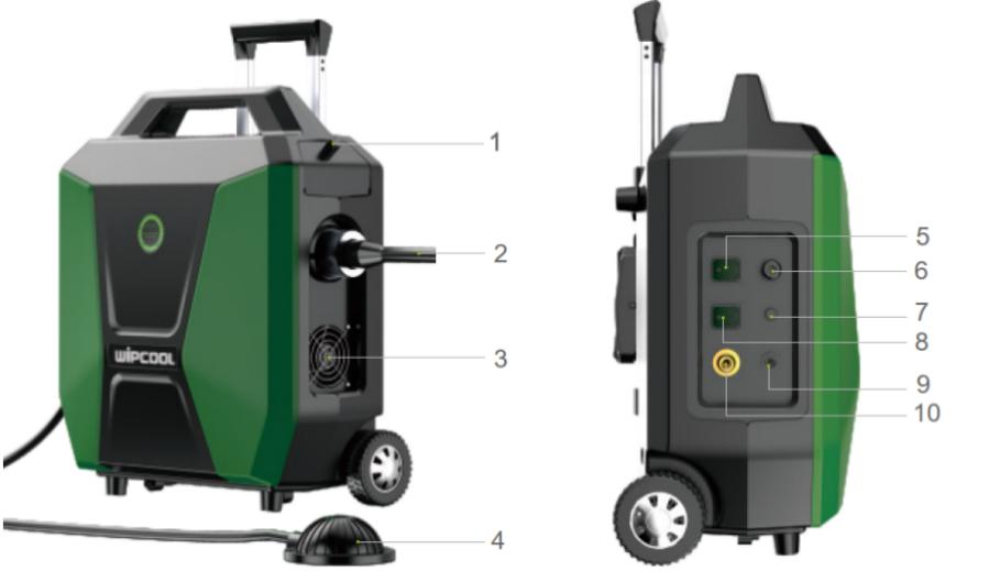
| No. | Name |
|---|---|
| 1 | Brush storage compartment |
| 2 | Flexible shaft |
| 3 | Fan |
| 4 | Foot switch |
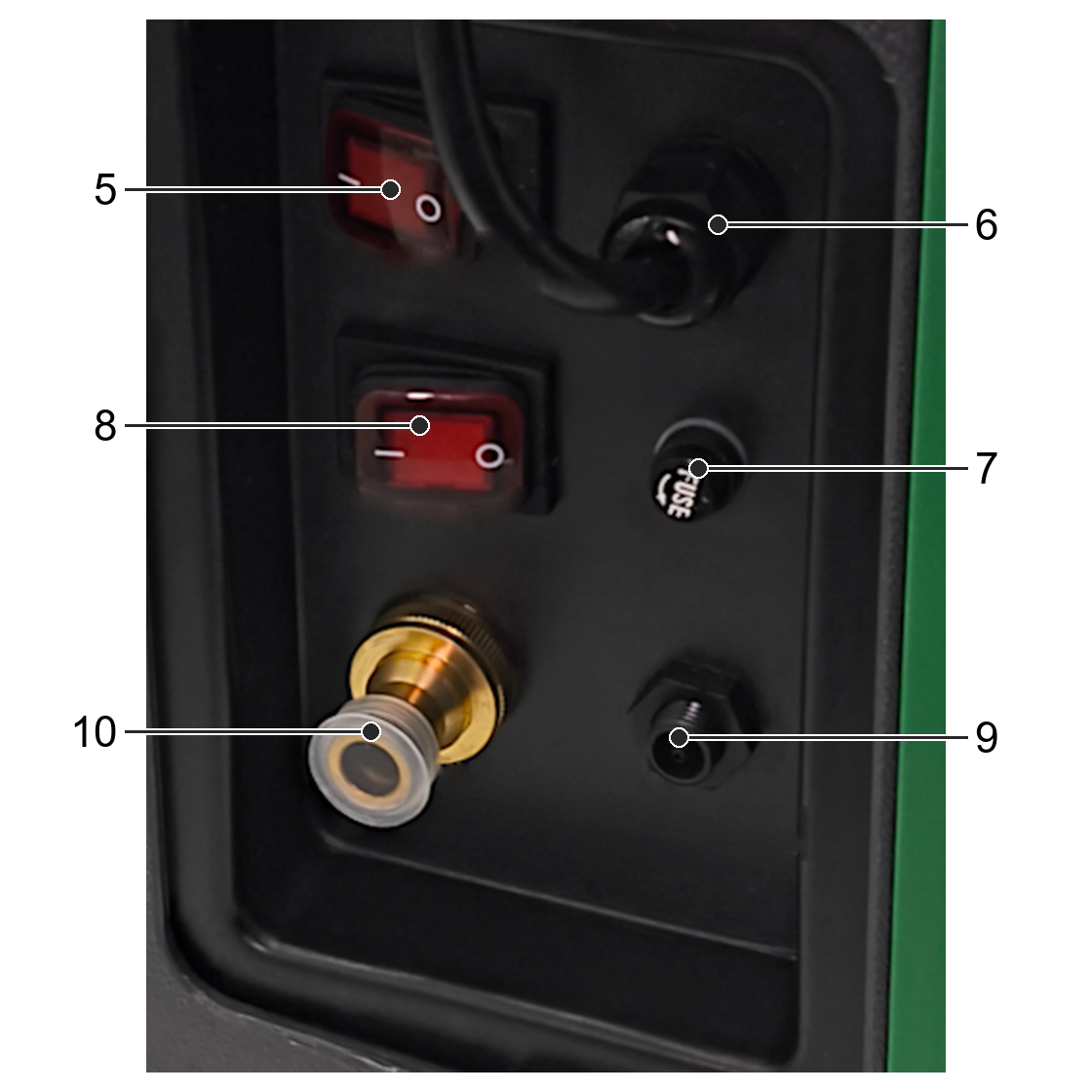
| 5 | Power switch |
| 6 | Power cable |
| 7 | Fuse |
| 8 | Manual shaft switch |
| 9 | Foot switch connection |
| 10 | Water inlet |
The shaft core is its inner rotating part, surrounded by a sheath. The drive coupling and self-priming pump are internal parts of the device.
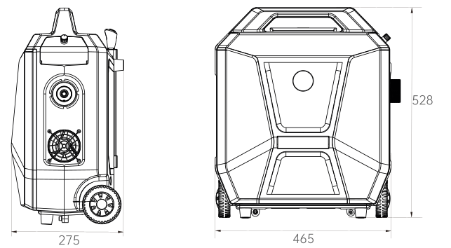
Device dimensions
Package contents
- ■CT370 device with 4 m power cable.
- ■12 mm flexible shaft, 7.6 m long.
- ■Two sets of brushes - 18 pieces in total.
- ■Foot switch.
- ■2 m inlet hose with inlet filter.
- ■Brass connector and plastic connector.
- ■Accessory bag.
- ■User manual.
After unpacking, check that the package is complete and in good condition. Report any missing items or transport damage to the seller.
Brush sizes
| Inch size | Manufacturer's metric size [mm] |
|---|---|
| 1/2" | 12.7 |
| 9/16" | 14.3 |
| 5/8" | 15.9 |
| 11/16" | 17.5 |
| 3/4" | 19.1 |
| 13/16" | 20.6 |
| 7/8" | 22.1 |
| 15/16" | 23.8 |
| 1" | 25.4 |
Transport and storage
Transport
- ■Transport the device in its original packaging. Do not throw it; protect it from impacts, excessive vibration, moisture, dust and extreme temperatures.
- ■Secure the device against tipping over and movement during transport.
Storage
Protect the device from frost. Water frozen in the pump can damage the pump head and motor.
- ■Store the device horizontally in a dry, well-ventilated room at 5–40 °C, away from direct sunlight and heat sources.
- ■Do not enclose a wet shaft in the bag or bend it tightly.
- ■Store the device out of the reach of children and untrained persons.
Application
The device removes scale and deposits from condenser and evaporator tubes in chillers. A dirty condenser may not achieve full cooling capacity or may operate at a higher pressure.
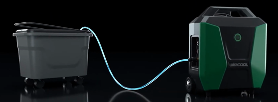
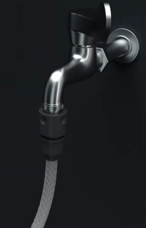
Water can be supplied from a tap or drawn from a tank.
Connection
- 01Disconnect the plug from the power supply. Keep the tap water supply shut off until all connections are complete.
- 02Connect the foot switch to the connection (item 9).
- 03Connect the inlet hose to the water inlet (item 10). Place the other end in a tank of clean water or connect it to a tap. Make sure the water supply is unobstructed and the inlet filter is clean.
- 04Fit the flexible shaft into the device's quick-release coupling. Check that the core is seated and the shaft is securely attached.
- 05Select a brush to match the diameter of the tube being cleaned and attach it to the end of the shaft.
How to use
- 01Place the device on a stable surface and position the shaft so that it cannot catch on anything. Insert the attached brush into the tube to be cleaned.
- 02If supplying water from a tap, turn on the water supply.
- 03Connect the device to the power supply and turn it on using the power switch. Use the foot switch to start and stop the drive; check that the shaft rotates correctly.
- 04Slowly advance the shaft into the tube. Water flowing through the shaft flushes out the debris.
- 05For heavier deposits, move the shaft back and forth; do not force the brush.
Finishing work
- 01Stop the drive and switch off the device. Disconnect the plug from the power supply and shut off the water supply, then remove the brush from the tube.
- 02Disconnect the inlet hose and shaft. Remove water from the shaft to prevent corrosion.
- 03Clean the brushes and inlet filter. Dry all parts before storing them.
Maintenance
General instructions
Clean the housing with a soft brush or cloth, without using water. Do not use alcohol, petrol, solvents, corrosive substances or strong detergents.
Maintenance procedure
- 01Remove the inlet filter from the inlet hose and clean its mesh. Remove debris from the brush end of the shaft and the ventilation openings.
- 02Check the shaft and its sheath for wear, cuts and leaks. Replace a worn shaft.
- 03Reinstall the inlet filter and the other removed parts. Check the fastenings and the condition of the device, accessories and power cable.
- 04Connect the device and check its operation, following the sequence in the ‘HOW TO USE’ section. If it does not work correctly, stop it, disconnect the power supply and shut off the water supply before inspection or correction. After making the correction, check its operation again.
Troubleshooting
Stop using the device if a fault requires repair by a service centre.
| Problem | Possible cause | Solution |
|---|---|---|
| Device does not operate | No power supply | Check the power connection. |
| Device does not operate | Incorrect voltage | Check that the supply voltage matches the rated voltage. |
| Device does not operate | Ambient temperature too low | Stop work and ensure an ambient temperature of 5–40 °C. |
| Water leaks from under the base | Leak in the water circuit | Check the inlet hose and connectors; tighten any loose connections. |
| Water leaks from under the base | Leaking seal where the shaft enters the device | Check where the shaft enters the device. Have it repaired by the service centre - submit a service request at wipcool.pl/serwis. |
| Device runs briefly or stops | Earth fault | Stop work, disconnect the power supply and have the installation and device inspected by qualified personnel. |
| Device runs briefly or stops | Overheating | Wait for the device to cool down, then restart it. |
| Motor runs, but the shaft or brush does not rotate | Damaged drive coupling | Have it repaired by the service centre - submit a service request at wipcool.pl/serwis. |
| Motor runs, but the shaft or brush does not rotate | Broken shaft | Have it repaired by the service centre - submit a service request at wipcool.pl/serwis. |
| No or low water flow through the shaft | Water supply shut off | Turn on the water supply. |
| No or low water flow through the shaft | Restricted hose | Check the inlet hose and remove any kinks or blockages. |
| No or low water flow through the shaft | Blocked inlet filter | Disconnect the inlet hose and clean the inlet filter mesh. |
| No or low water flow through the shaft | Ambient temperature too low | Ensure an ambient temperature of 5–40 °C. |
| No or low water flow through the shaft | Damaged self-priming pump | Have it repaired by the service centre - submit a service request at wipcool.pl/serwis. |
| Leaks at connections | Damaged seal | Check the seal and replace it if damaged. |
| Leaks at connections | Loose connection | Check and tighten the connection. |
| Noisy operation | Air being drawn in | Check the water level in the tank, that the end of the inlet hose is submerged, and the condition of the hose. |
| Noisy operation | Damaged internal parts | Have it repaired by the service centre - submit a service request at wipcool.pl/serwis. |
| Foot switch does not start or stop the drive | Faulty foot switch | Stop using the device. Have it repaired by the service centre - submit a service request at wipcool.pl/serwis. |
Waste electrical and electronic equipment
- 01The crossed-out bin symbol means that the device must not be disposed of with other waste at the end of its life.
Under the applicable regulations on waste electrical and electronic equipment, products marked with the separate collection symbol must not be disposed of with other municipal waste. Because they contain hazardous substances, electronic products that are not separately sorted may pose a risk to the environment and human health. Proper separate collection of waste electrical and electronic equipment prevents adverse effects on the environment.
By taking waste equipment to a collection point, the user contributes to its reuse, recycling and recovery.
Recycling - one method of protecting the environment. The process of recovering substances from waste for reuse as raw materials.
Waste recovery - the use of waste that has lost its useful value as secondary raw materials, for example plastics, paper and cardboard; the term is also commonly used to refer to waste destruction.
Information on the collection system for waste electrical and electronic equipment
- ■Waste electrical and electronic equipment must not be disposed of with other waste.
- ■The collection of incomplete electrical and electronic equipment and parts from waste equipment is prohibited.
- ■A distributor delivering equipment intended for households to a purchaser must collect waste equipment from households free of charge at the place of delivery, provided that the waste equipment is of the same type and performs the same function as the equipment delivered.
- ■The user may hand over waste equipment to a waste equipment collector, a treatment facility or a municipal waste collector in the municipality.
- ■Information on collection points is available on the Public Information Bulletin (BIP) websites of regional, city and municipal offices.
Service and documents
Before submitting a service request, prepare:
- ■Model - found on the device's data plate and on the invoice.
- ■Serial number - if absent, provide the production number (e.g. 11/2025), usually found on the underside of the device.
- ■Proof of purchase - an invoice or receipt from an authorised distributor.
- ■Description of the fault - what is happening, since when and under what conditions.
You can submit a service request at wipcool.pl/serwis. You will also find the warranty terms there.