 Distribution PL · 4REF
Wipcool MRM55 user manual
Read the entire manual before first use. Keep it for as long as you use the device.
Wipcool MRM55/MRM55OS user manual
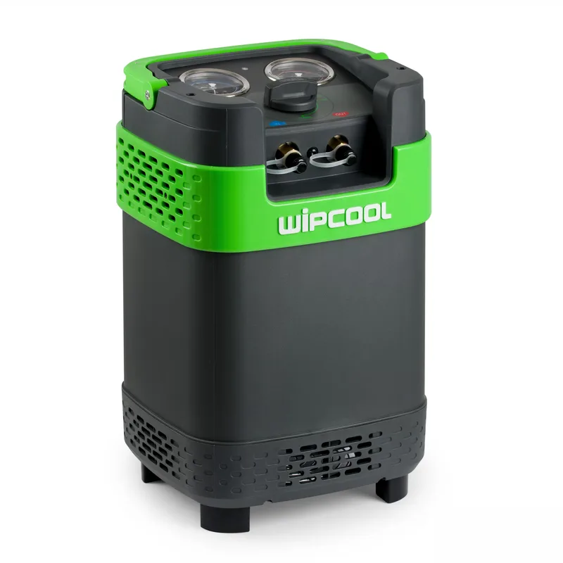
The Wipcool MRM55/MRM55OS refrigerant recovery machine is used to recover refrigerant from air conditioning and refrigeration systems. The MRM55OS has a built-in oil separator.
The user manual is an integral part of the product. Please read this manual carefully and follow all instructions closely.
General information
Wipcool products are designed for professional use by qualified air conditioning and refrigeration engineers. As the manufacturer, Wipcool stipulates that our equipment should only be operated by suitably qualified and trained personnel.
- ■Comply with all local safety regulations and general safety standards when using the Wipcool MRM55/MRM55OS refrigerant recovery machine.
- ■The user manual should be kept near the machine so that personnel can access it easily at all times.
- ■Before use, qualified personnel should read the user manual carefully and understand all the instructions it contains.
- ■The manufacturer accepts no liability for any damage resulting from improper use, failure to follow the user manual, lack of personnel qualifications or any unauthorised modifications to the machine.
- ■The general terms of sale contained in the sales documents apply.
Symbols and conventions
Symbols and markings used on the machine and in the manual:
- 01
 Warning - read the text in the box next to the symbol.
- 02
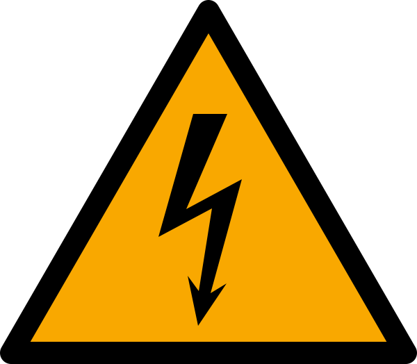 Hazardous voltage - risk of electric shock.
- 03
 Low temperature - protect skin and eyes from refrigerant.
- 04
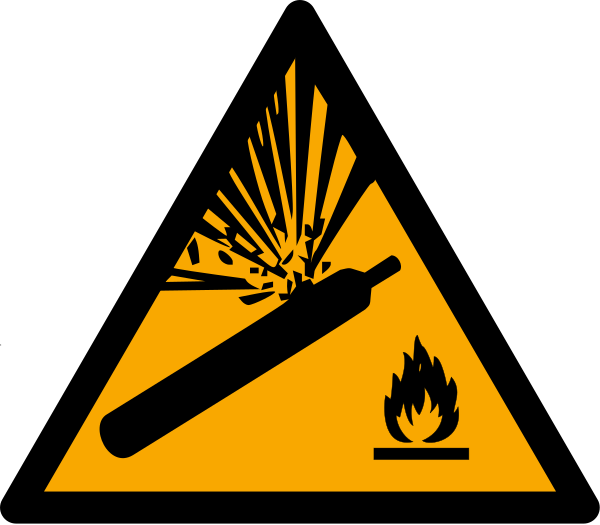 Pressurised gas cylinder - risk of rupture if overfilled.
- 05
 Notice - risk of damage to the machine or incorrect results.
- 06
 Before starting work, read all safety and installation instructions carefully.
- 07
 Indicates that the product meets the health, safety and environmental standards applicable in the European Union.
- 08RoHSThe product meets the requirements for restricting the use of hazardous substances.
- 09
 Do not dispose of the machine with household waste.
Safety information
General rules
- ■Ensure the room is well ventilated. Do not expose the machine to sunlight or rain.
- ■Place the machine on a level surface. Tilting during operation increases vibration, noise and wear on parts.
- ■The inlet pressure indicated by the low-side gauge must not exceed 26 bar.
- ■Do not mix different refrigerants in one cylinder. They cannot be separated or used afterwards.
Technical specifications
Refrigerants
| Group | Refrigerants |
|---|---|
| III | R12, R134a, R401C, R406A, R500, R1234yf |
| IV | R22, R401A, R401B, R402B, R407C, R407D, R408A, R409A, R411A, R411B, R412A, R502, R509 |
| V | R402A, R404A, R407A, R407B, R410A, R507, R32 |
Recovery rate
| State / method | Group III | Group IV | Group V |
|---|---|---|---|
| Vapour | 0.22 kg/min | 0.25 kg/min | 0.25 kg/min |
| Liquid | 1.8 kg/min | 2.0 kg/min | 2.2 kg/min |
| Push/Pull | 5.0 kg/min | 6.0 kg/min | 6.5 kg/min |
Machine diagram
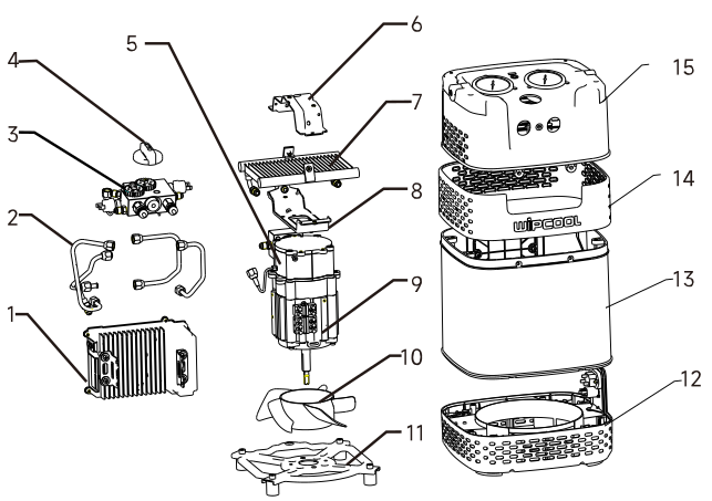
| No. | Name |
|---|---|
| 1 | Motor controller |
| 2 | Copper tube |
| 3 | Control valve |
| 4 | Knob |
| 5 | Compressor |
| 6 | Control valve handle |
| 7 | Condenser |
| 8 | Upper support plate |
| 9 | Motor |
| 10 | Fan |
| 11 | Lower support plate |
| 12 | Lower housing |
| 13 | Housing body |
| 14 | Housing ring |
| 15 | Upper housing |
Controls
| Component | Function |
|---|---|
| ON/OFF button | Switches the machine on and off. |
| Low-side gauge | Shows the compressor inlet pressure. |
| High-side gauge | Shows the compressor outlet pressure. |
| Status indicator | Flashes red when the high-pressure protection trips. Flashing green is one of the conditions for restarting the machine. |
| Inlet port | Connection for the hose from the manifold gauge set during liquid and vapour recovery (Figure 3). |
| Outlet port | Connection for the hose to the cylinder during liquid and vapour recovery (Figure 3). |
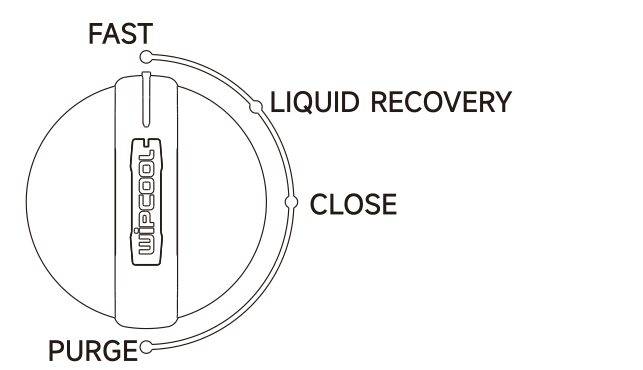
| Position | Use |
|---|---|
| LIQUID RECOVERY (liquid recovery) | Start of liquid and vapour recovery. |
| FAST (fast recovery) | Faster recovery of remaining vapour after liquid recovery; also the operating position for Push/Pull. |
| CLOSE (closed) | Closes the machine when it is not running. |
| PURGE (machine purge) | Removes remaining refrigerant from the machine after recovery. |
Package contents
- ■MRM55 or MRM55OS machine.
- ■User manual.
- ■1.8 m power cable.
- ■Filter drier.
- ■Shoulder strap.
- ■Service hose.
After unpacking, check that the package is complete and in good condition. Report any missing or damaged items to the seller.
Equipment required for recovery but not included
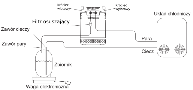
Prepare a recovery cylinder, electronic scales, a manifold gauge set and additional hoses for the connections shown in Figures 3 and 4.
Transport and storage
Transport the machine in its original packaging. Store it in a dry place, away from sunlight and heat sources, at a temperature of -20 to +60 °C.
Remove the remaining refrigerant before long-term storage. When the machine is not running, close the valves, set the knob to CLOSE and fit caps to the inlet and outlet ports. Air and moisture impair recovery and shorten the life of the machine.
Connection
Preparing for recovery
- ■Before first use, remove the factory-filled nitrogen from the cylinder. Before recovery, evacuate the cylinder to approximately -1 bar relative to atmospheric pressure to remove non-condensable gases.
- ■Always use a filter drier intended for this machine at its inlet port; one is included. Use a separate filter drier for each type of refrigerant and replace it regularly. When recovering from a system after a compressor burnout, use two filter driers.
- ■For fast recovery, use a hose with an internal diameter greater than 4 mm and a length of no more than 1.5 m. A hose that is too narrow or too long slows recovery.
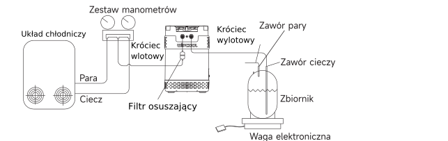
- 01Set the knob to LIQUID RECOVERY, then connect the hoses as shown in Figure 3 and tighten the connections.
- 02Connect the machine to the power supply.
Operation
Liquid and vapour recovery
- 01Once the machine is connected, start it using the ON/OFF button.
- 02Open the cylinder valve connected to the machine outlet port. Open the liquid valve on the manifold gauge set to start recovery.
- 03When liquid recovery is complete, set the knob to FAST to speed up recovery of the remaining vapour.
- 04Recover refrigerant until the required vacuum is reached or the machine stops automatically. Then proceed to purge the machine in PURGE mode.
After a power failure or if the machine is difficult to start, set the knob to LIQUID RECOVERY before switching it on again.
Purging the machine - PURGE
- 01Do not disconnect the power supply after recovery. Set the knob to PURGE and leave the machine running until the required vacuum is reached. Purging is then complete.
- 02Close the cylinder valve and the outlet hose shut-off valve, if fitted.
- 03Close the valves on the manifold gauge set, then close the valve between the refrigeration system and the manifold gauge set.
- 04Switch off the machine using the ON/OFF button and disconnect the power supply. Carefully and slowly disconnect all hoses.
- 05Set the knob to CLOSE and fit caps to the machine inlet and outlet ports.
Push/Pull
The Push/Pull method is used for large systems containing more than 10 kg of liquid refrigerant. Figure 4 shows the connections.
High-pressure protection
The machine switches off automatically when the pressure exceeds 38.5 bar. Before restarting, find and correct the cause of the protection trip.
| Possible cause | Solution |
|---|---|
| Cylinder inlet valve closed | Open the cylinder valve. |
| Cylinder temperature too high | Allow the cylinder to cool naturally and the pressure to fall. |
- 01Check the high-side gauge - the pressure must fall below 30 bar.
- 02Wait until the status indicator starts flashing green. Once both conditions are met, press the ON/OFF button.
Maintenance
Clean the filter screen in the inlet port regularly. Replace a damaged screen with a new one.
Troubleshooting
| Problem | Possible cause | Solution |
|---|---|---|
| The compressor does not start when the power is switched on or stops after a few minutes. | The high-pressure protection has tripped. | Follow the ‘High-pressure protection’ procedure. |
| The compressor does not start when the power is switched on or stops after a few minutes. | Motor or other electrical component failure. | Have the machine repaired by the service centre - submit a request at wipcool.pl/serwis. |
| The compressor does not start. | Outlet pressure too high. | Set the knob to LIQUID RECOVERY before switching on again. If the machine still does not start, do not attempt to start it again. Have the machine repaired by the service centre - submit a request at wipcool.pl/serwis. |
| Recovery is too slow. | Outlet pressure too high. | Allow the cylinder to cool naturally and the pressure to fall. |
| Recovery is too slow. | Worn compressor seals. | Have the machine repaired by the service centre - submit a request at wipcool.pl/serwis. |
| The machine does not create a vacuum. | Loose hose connections. | Tighten the hose connections. |
| The machine does not create a vacuum. | Leak in the machine. | Have the machine repaired by the service centre - submit a request at wipcool.pl/serwis. |
Waste electrical and electronic equipment
- 01The crossed-out bin symbol means that the device must not be disposed of with other waste at the end of its life.
Under applicable waste electrical and electronic equipment regulations, products marked with the separate collection symbol must not be disposed of with other municipal waste. Because they contain harmful substances, electronic products that are not sorted separately can be hazardous to the environment and human health. Proper separate collection of waste electrical and electronic equipment prevents adverse effects on the environment.
By taking waste equipment to a collection point, you contribute to its reuse, recycling and recovery.
Recycling - a method of protecting the environment. The process of recovering substances from waste that can be reused as raw materials.
Waste utilisation - the use of waste that has lost its useful value as secondary raw materials, for example plastics, paper and cardboard; the term is also commonly used to mean its destruction.
Information on the waste electrical and electronic equipment collection system
- ■Waste electrical and electronic equipment must not be disposed of with other waste.
- ■The collection of incomplete electrical and electronic equipment and parts from waste equipment is prohibited.
- ■A distributor delivering equipment intended for households to a purchaser must collect waste equipment from households free of charge at the place of delivery, provided that the waste equipment is of the same type and performs the same function as the equipment supplied.
- ■You can hand over waste equipment to a waste equipment collector, a treatment facility or a municipal waste collector in your municipality.
- ■Information about collection points is available on the Public Information Bulletin (BIP) websites of regional, city and municipal authorities.
Service and documents
Before submitting a request, prepare:
- ■Model - found on the machine rating plate and on the invoice.
- ■Serial number - if there is none, provide the production number (e.g. 11/2025), usually found on the underside of the machine.
- ■Proof of purchase - an invoice or receipt from an authorised distributor.
- ■Description of the fault - what is happening, when it started and under what conditions.
You can submit a service request at wipcool.pl/serwis. You will also find the warranty terms there.