
 Distribution PL · 4REF
Wipcool MVG-1 user manual
Read the entire manual before first use. Keep it for as long as you use the device.
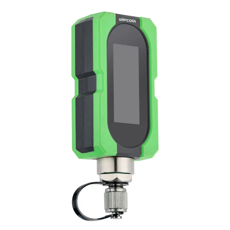
Wipcool MVG-1 user manual
The Wipcool MVG-1 is a digital vacuum gauge for measuring vacuum in air conditioning and refrigeration systems. It is powered by a built-in lithium battery and has a 1/4" SAE connection.
The user manual is an integral part of the product. Please read this manual carefully and follow all instructions closely.
General information
Wipcool products are designed for professional use by qualified air conditioning and refrigeration engineers. As the manufacturer, Wipcool stipulates that our equipment should only be operated by suitably qualified and trained personnel.
- ■Comply with all local safety regulations and general safety standards when using the Wipcool MVG-1 Vacuum Gauge.
- ■The user manual should be kept near the device so that personnel can access it easily at any time.
- ■Before use, qualified personnel should read the user manual carefully and understand all the instructions it contains.
- ■The manufacturer accepts no liability for any damage resulting from improper use, failure to follow the user manual, insufficiently qualified personnel or any unauthorised modifications to the device.
- ■The general terms of sale set out in the sales documents apply.
Symbols and conventions
Signs and markings used on the device and in the manual:
- 01
 Notice - risk of damage to the device or an incorrect result.
- 02
 Tip: advice on operating the device.
- 03
 Indicates that the product meets the health, safety and environmental standards applicable in the European Union.
- 04RoHSThe product meets the requirements for restricting the use of hazardous substances.
- 05
 Do not dispose of the device with household waste.
Safety information
- ■Do not use the device if it is damaged or not working properly.
- ■Protect the vacuum gauge from shocks and falls. Avoid contact with water or other liquids, except when cleaning the sensor chamber as described in the ‘MAINTENANCE’ section.
Technical specifications
| Range [microns] | Resolution [microns] | Accuracy |
|---|---|---|
| 1–400 | 1 | ±10% of reading ±10 microns |
| 400–3 000 | 10 | ±10% of reading ±10 microns |
| 3 000–10 000 | 100 | ±10% of reading ±10 microns |
| 10 000–19 000 | 250 | ±20% of reading |
Device diagram
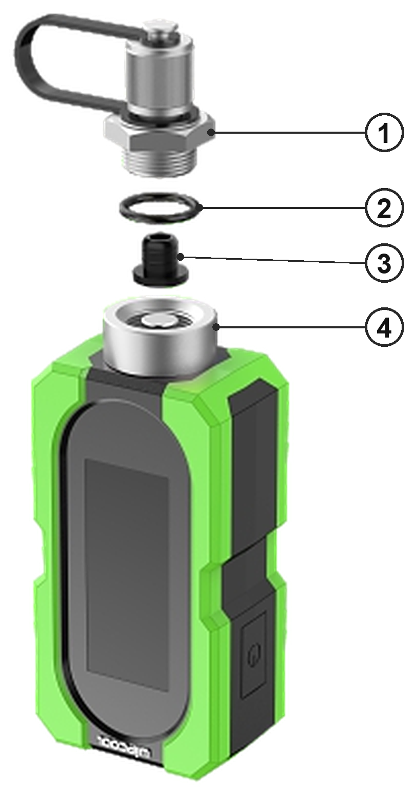
The POWER button is used to switch on the vacuum gauge and change settings. The USB-C port is used for charging.
Display
TH₂O indicates the water saturation temperature corresponding to the vacuum in the system, and Tamb indicates the ambient temperature. The word microns on the display means microns.
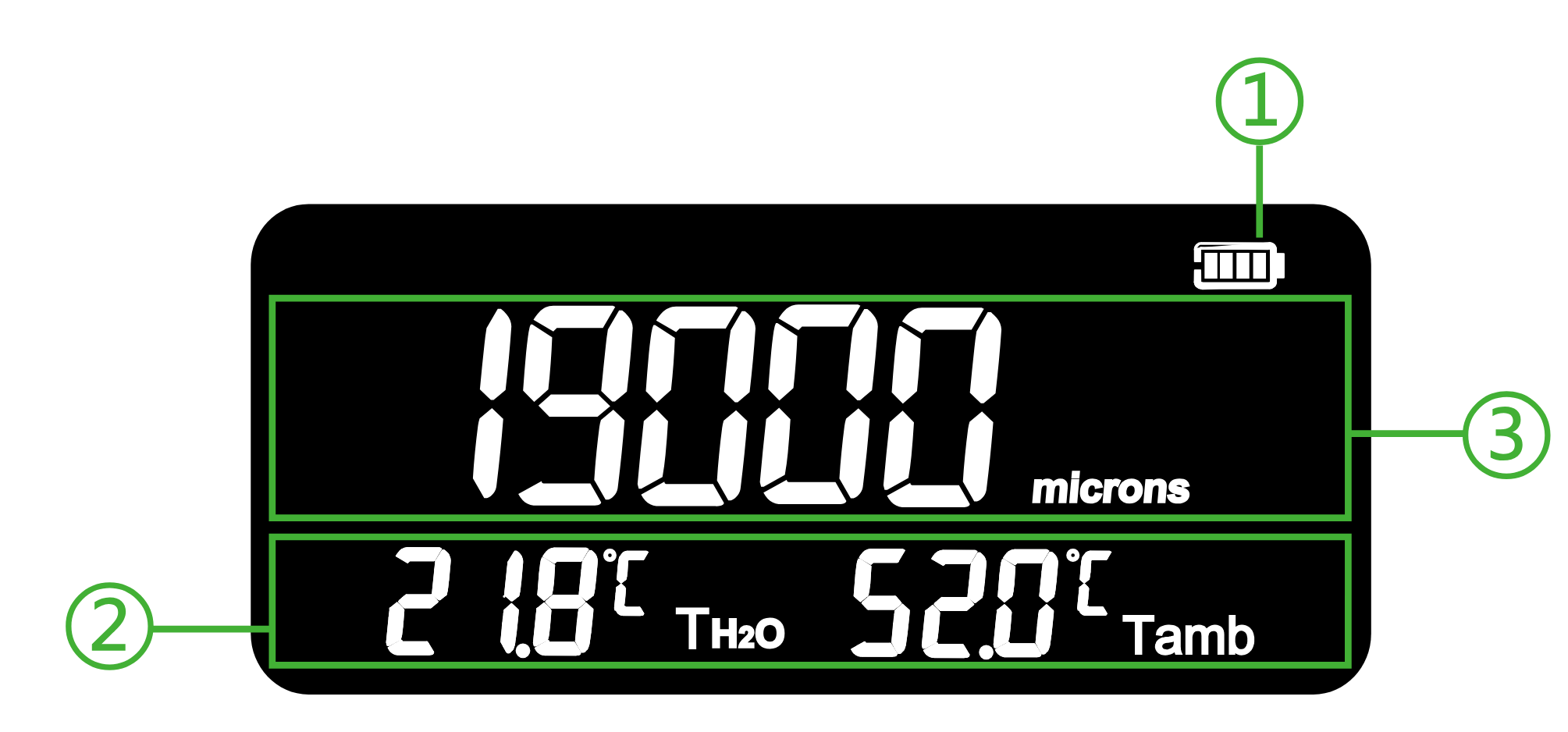
| No. | Meaning |
|---|---|
| 1 | Battery charge level. |
| 2 | TH₂O and Tamb temperature readings. |
| 3 | Current vacuum reading and selected unit. |
Battery charge level
- 01
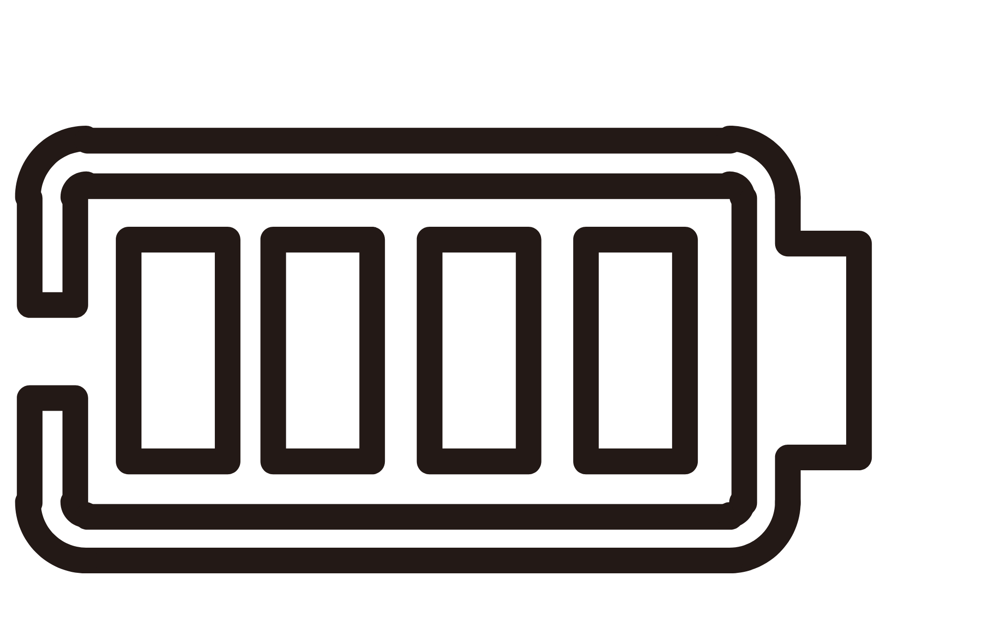 Above 75%
- 02
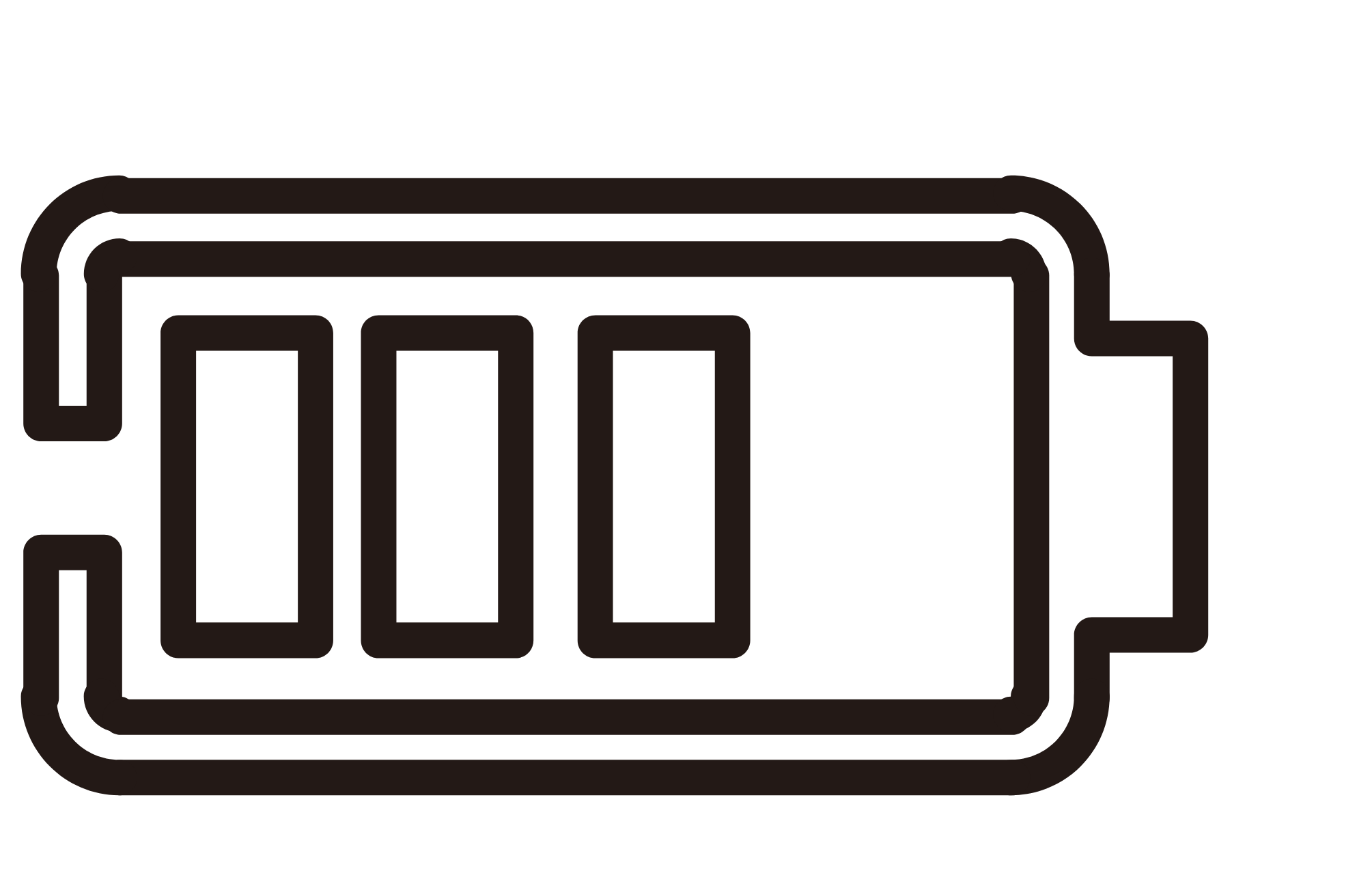 Above 50%
- 03
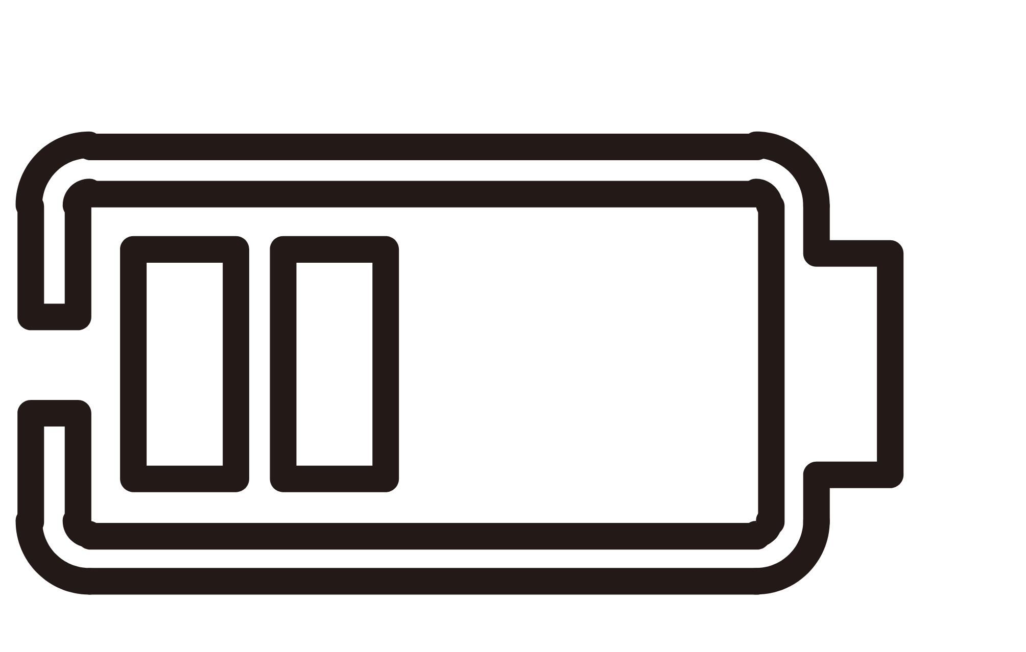 Above 25%
- 04
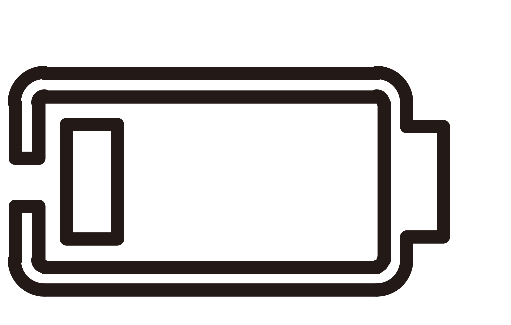 Above 5%
- 05
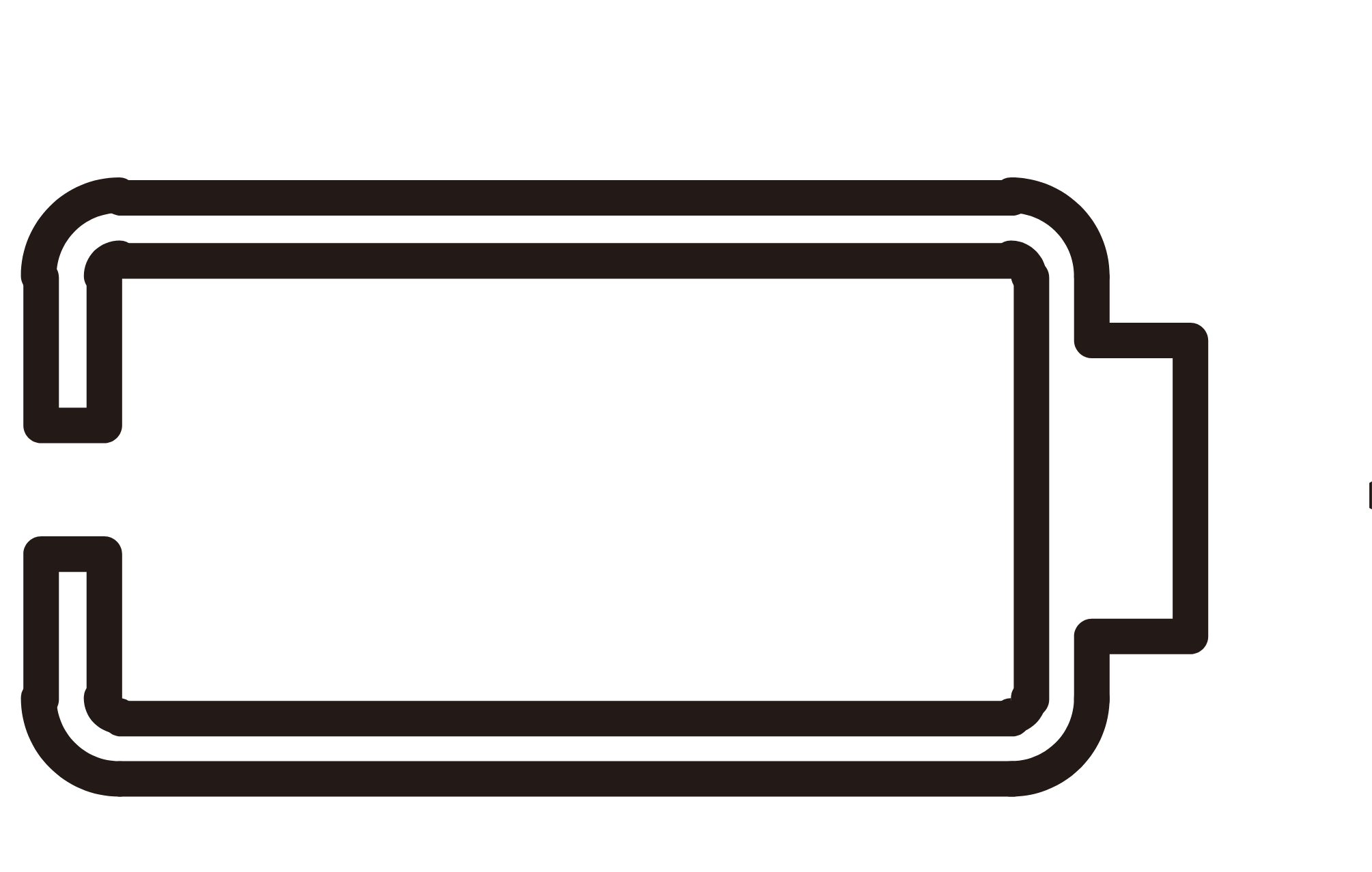 Below 5%
Package contents
After unpacking, check that all items are present and in good condition. Report any missing or damaged items to the seller.
- ■MVG-1 vacuum gauge.
- ■Protective cover.
- ■1/4" × 1/4" SAE extension, female.
- ■1/4" SAE tee, M-F-M (male - female - male).
- ■O-rings.
- ■Rubber seals.
- ■Oil filters.
- ■User manual.
Transport and storage
Transport the device in its original packaging. Store it in a dry, ventilated place, away from direct sunlight and heat sources, at a temperature of -20–+60 °C.
Application
The vacuum gauge is used to monitor vacuum while removing moisture and other substances from air conditioning and refrigeration systems.
Connection
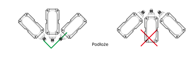
- 01Connect the vacuum gauge to the system via the 1/4" SAE connection. Where possible, position it vertically with the connection pointing downwards.
Operation
Charging the battery
- 01To charge the battery, connect a USB-C cable to the charging port on the vacuum gauge.
Switching on and measuring
- 01Press POWER to switch on the vacuum gauge.
At atmospheric pressure, ‘-----’ is displayed. When the pressure is within the range of 1–19 000 microns, the current value appears on the display.
Setting the units
- 01With the device switched on, briefly press POWER to enter vacuum unit selection. Use successive short presses to select a unit: mTorr, inHg, Pa, Torr, kPa, mbar, psia or microns.
- 02When the vacuum unit is flashing, press and hold POWER to enter the temperature unit settings.
- 03When the temperature unit symbol is flashing, briefly press POWER to select °C.
The device saves the settings automatically.
H₂O water state
The vacuum gauge determines the state of water by comparing the ambient temperature Tamb with the water saturation temperature TH₂O corresponding to the vacuum in the system. When TH₂O is lower than Tamb, water evaporates, allowing the system to be dried more effectively.
Maintenance
General recommendations
Carry out maintenance after disconnecting the vacuum gauge from the system. Before starting, switch off the vacuum gauge and disconnect it from the charger.
The oil filter traps contaminants and limits sensor contamination. Check the filter every 3 months under normal use; adjust the inspection frequency to the intensity of use. Also check the condition of the O-ring regularly.
Inspecting the filter and O-ring
- 01Unscrew the sensor nut with a spanner and remove the oil filter.
- 02Replace the oil filter if it is heavily contaminated.
- 03Check the condition of the O-ring. Replace a damaged O-ring; lubricate the new one with vacuum pump oil before fitting it.
- 04Insert the oil filter into the sensor nut and tighten the nut with a spanner.
Cleaning the sensor chamber
- 01Unscrew the sensor nut. Use a pipette or syringe to introduce the liquid into the sensor chamber.
- 02Tighten the sensor nut and gently shake the vacuum gauge.
- 03Loosen the sensor nut and pour the liquid out of the sensor chamber. Repeat the rinse 3–4 times.
- 04Dry the sensor by evacuation or leave it exposed to air for 3 h until dry.
Troubleshooting
| Problem | Possible cause | Solution |
|---|---|---|
| No vacuum reading | Vacuum gauge not connected to the system | Check the connection between the vacuum gauge and the system. |
| Incorrect readings | Contaminated sensor | Clean the sensor chamber as described in the ‘MAINTENANCE’ section. |
| Device switches off | Low battery charge | Charge the battery via the USB-C port. |
Waste electrical and electronic equipment
- 01The crossed-out bin symbol means that the device must not be disposed of with other waste at the end of its life.
Under the applicable regulations on waste electrical and electronic equipment, products marked with the separate collection symbol must not be disposed of with other municipal waste. Because they contain harmful substances, electronic products that are not collected and sorted separately may be hazardous to the environment and human health. Proper separate collection of waste electrical and electronic equipment prevents adverse effects on the environment.
By taking waste equipment to a collection point, the user contributes to its reuse, recycling and recovery.
Recycling - a method of protecting the environment. The process of recovering substances from waste that can be reused as raw materials.
Waste recovery - the use of waste that has lost its useful value, such as plastics, paper and cardboard, as secondary raw materials (also commonly understood to include destruction).
Information about the waste electrical and electronic equipment collection system
- ■Waste electrical and electronic equipment must not be disposed of with other waste.
- ■The collection of incomplete electrical and electronic equipment and parts from waste equipment is prohibited.
- ■A distributor delivering equipment intended for households to a purchaser must collect waste equipment from households free of charge at the delivery location, provided that the waste equipment is of the same type and performs the same function as the equipment delivered.
- ■The user may hand over waste equipment to a waste equipment collector, a treatment facility or a municipal waste collector in the municipality.
- ■Information about collection points is available on the Public Information Bulletin (BIP) websites of regional, city and municipal offices.
Batteries
- 01The crossed-out bin symbol on a battery means that it must be collected separately from other waste at the end of its life. Batteries must not be disposed of with municipal waste.
- ■Take used batteries to a collection point. If possible, remove them from the device before taking it for collection.
- ■Substances contained in batteries can harm the environment and health, especially if a battery is damaged or leaking. Separate collection allows them to be processed safely and raw materials to be recovered.
- ■The Cd or Pb marking under the bin symbol means that the battery contains more than 0.002% cadmium or more than 0.004% lead.
The MVG-1 vacuum gauge battery is built in - do not remove it yourself. Take the vacuum gauge and its battery to a collection point.
Service and documents
Before submitting a request, prepare:
- ■Model - shown on the device nameplate and on the invoice.
- ■Serial number - if there is none, provide the production number (e.g. 11/2025), usually found on the underside of the device.
- ■Proof of purchase - an invoice or receipt from an authorised distributor.
- ■Description of the fault - what is happening, when it started and under what conditions.
You can submit a service request at wipcool.pl/serwis. You will also find the warranty terms there.