
 Distribution PL · 4REF
Wipcool P30J user manual
Read the entire manual before first use. Keep it for as long as you use the device.
Wipcool P30J user manual
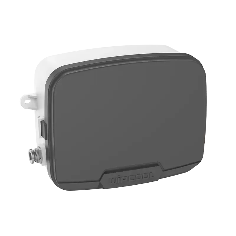
The Wipcool P30J Condenser Misting System cools air conditioner outdoor units with a water mist. The controller supplies pressurised water to five nozzles and controls misting based on temperature and the current sensor signal.
The user manual is an integral part of the product. Please read this manual carefully and follow all instructions closely.
General information
Wipcool products are designed for professional use by qualified air conditioning and refrigeration engineers. As the manufacturer, Wipcool stipulates that our equipment should only be operated by appropriately qualified and trained personnel.
- ■Comply with all local safety regulations and general safety standards when using the Wipcool P30J Condenser Misting System.
- ■The user manual should be kept near the device so that personnel can easily access it at any time.
- ■Before use, qualified personnel should read the user manual carefully and understand all the instructions it contains.
- ■The manufacturer accepts no liability for any damage resulting from improper use, failure to follow the user manual, insufficiently qualified personnel or any unauthorised modifications to the device.
- ■The general terms of sale contained in the sales documents apply.
Symbols and conventions
Signs and markings used on the device and in the manual:
- 01
 Hazardous voltage - risk of electric shock.
- 02
 Notice - risk of damage to the device or an incorrect result.
- 03
 Do not dispose of the device with household waste.
Safety information
- ■Sand and sediment in the water block the nozzles, so use a pre-filter. If necessary, use soft, purified water.
- ■Ensure an inlet water pressure of 2–8 bar. If the pressure is below 2 bar, use a booster pump.
- ■Do not use the device or accessories if damaged. If damage occurs, stop using them. Have them repaired by the service centre - submit a service request at wipcool.pl/serwis.
- ■Before disconnecting the water lines, shut off the water supply and release the pressure.
Technical specifications
Water consumption with five nozzles
| Inlet water pressure [bar] | Water consumption [l/h] |
|---|---|
| 2 | 18 |
| 4 | 33 |
| 6 | 44 |
| 8 | 53 |
Device diagram
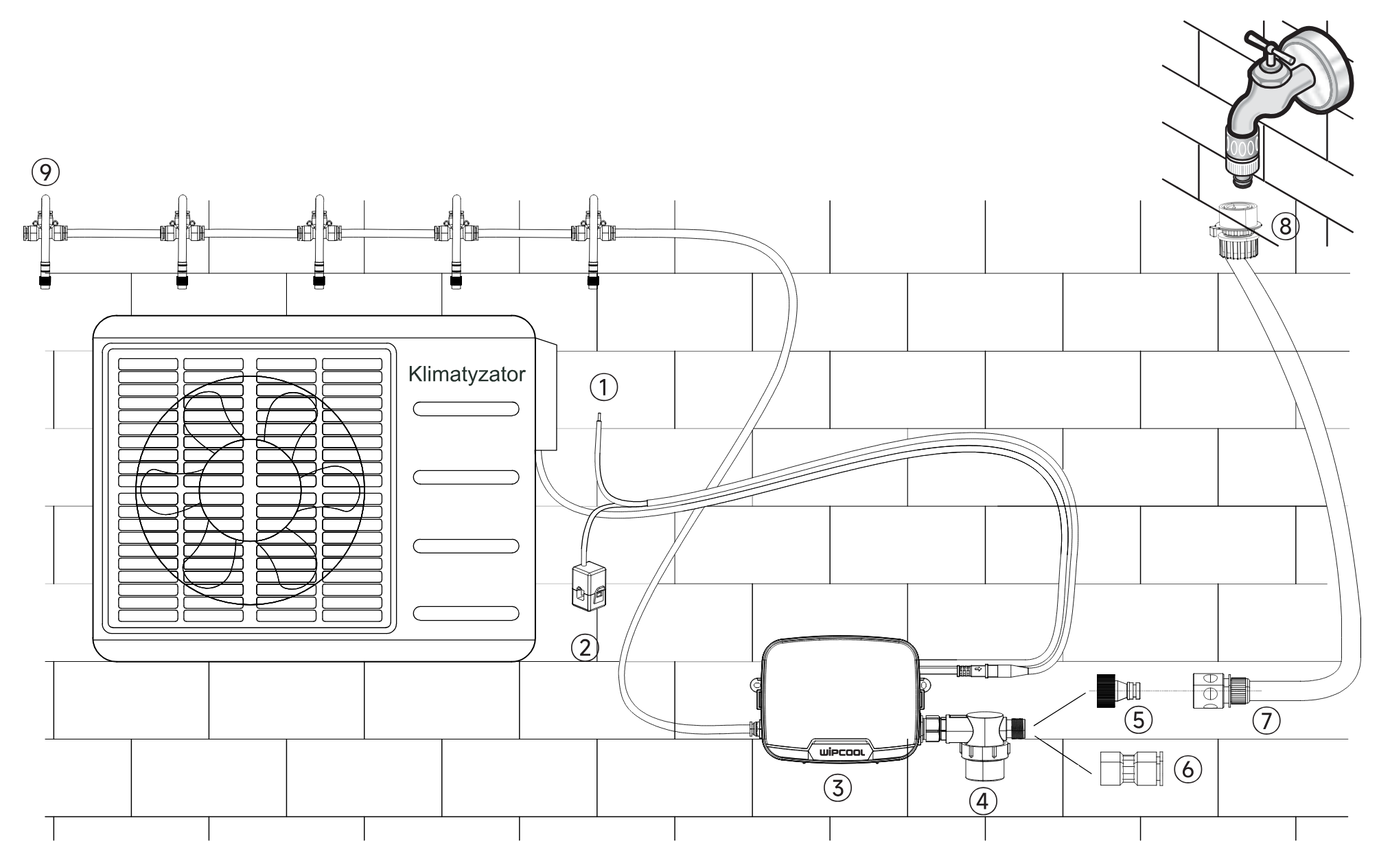
| No. | Name |
|---|---|
| 1 | Temperature sensor |
| 2 | Current sensor |
| 3 | Misting controller |
| 4 | Pre-filter |
| 5 | 1/2" PT female threaded connector |
| 6 | 20 mm pipe connector |
| 7 | 1/2" garden hose quick-release coupling |
| 8 | 1/2" tap connector with seal |
| 9 | Adjustable misting nozzles |
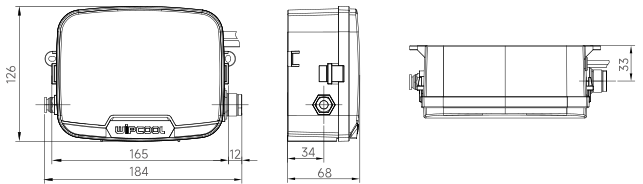
Controller dimensions
Package contents
After unpacking, check that the set is complete and in good condition. Report any missing or damaged items to the seller.
| Item | Quantity |
|---|---|
| P30J controller with temperature and current sensors | 1 set |
| 1/2" PT female threaded connector | 1 pc. |
| 1/2" garden hose quick-release coupling | 1 pc. |
| Rotating nozzle with tee, 20 cm | 4 pcs. |
| 20 mm pipe connector | 1 pc. |
| 1/2" tap connector with seal | 1 pc. |
| End rotating nozzle adjustable in two directions, 20 cm | 1 pc. |
| 5 m outlet hose | 1 pc. |
| Pre-filter | 1 pc. |
| Mounting plate | 1 pc. |
| Plastic wall plug | 2 pcs. |
| Screw | 2 pcs. |
| User manual | 1 pc. |
Installation
Mounting the controller
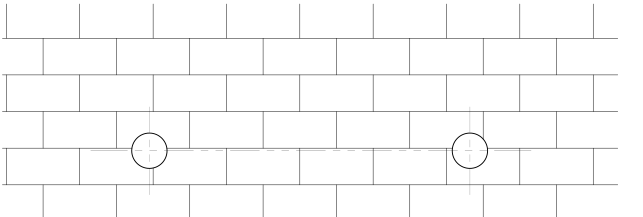
- 01Select a mounting location and drill 6 mm diameter holes.
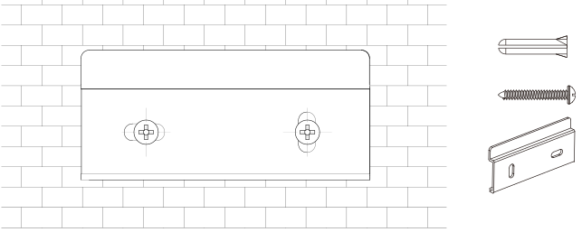
- 02Attach the mounting plate to the wall and secure the controller.
Water supply and nozzles
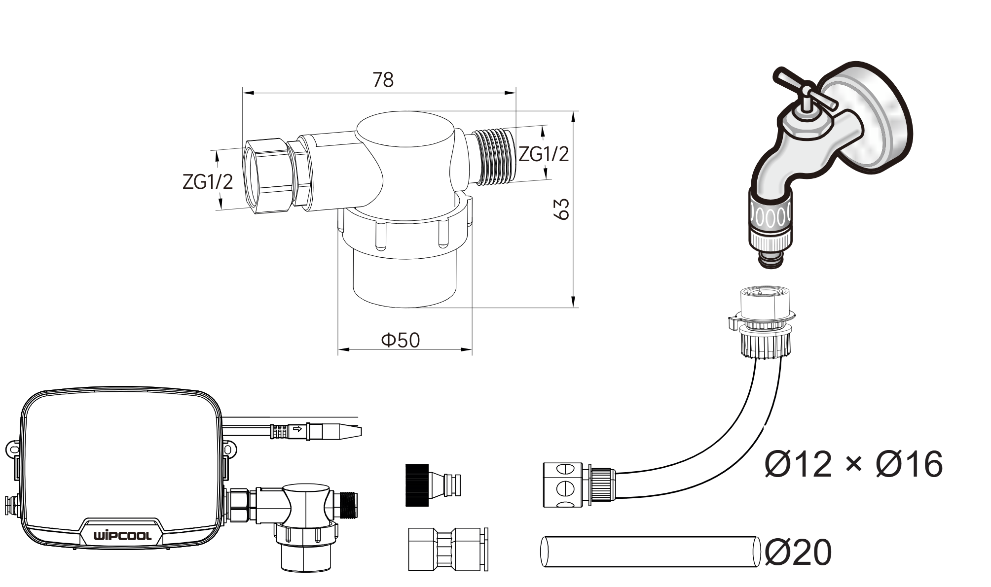
- 01Select the connector for a Ø12 × Ø16 mm hose or a rigid Ø20 mm pipe.
- 02Install the pre-filter upstream of the controller and connect the water supply.
- 03Connect the controller outlet to the 5 m outlet hose and the set of five nozzles as shown in figure 1.
Connection
Power supply
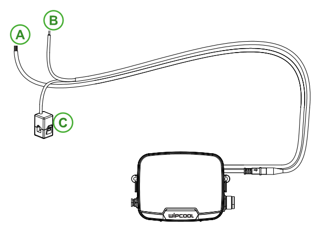
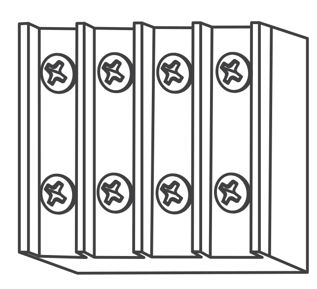
Connect the P30J power cable to the appropriate L (live), N (neutral) and PE (protective earth) terminals of the air conditioner outdoor unit, in accordance with the markings and the unit documentation.
Temperature sensor
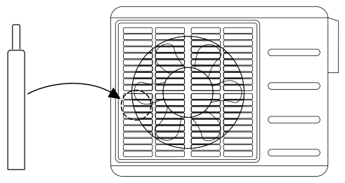
Place the NTC-10K (10 kΩ) temperature sensor on the fins of the outdoor unit coil. Choose a location where water from the nozzles will not fall directly onto it.
Current sensor
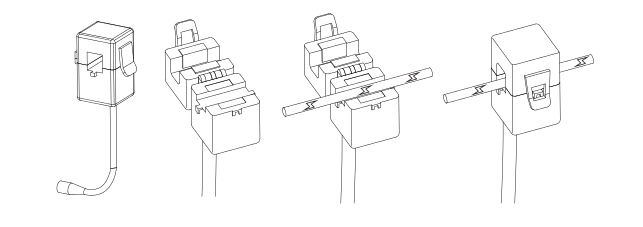
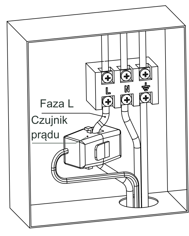
Open the current sensor, place it around a single L live conductor and close it, as shown in figure 9. Do not place it around the entire multicore cable.
Operation
Panel and settings
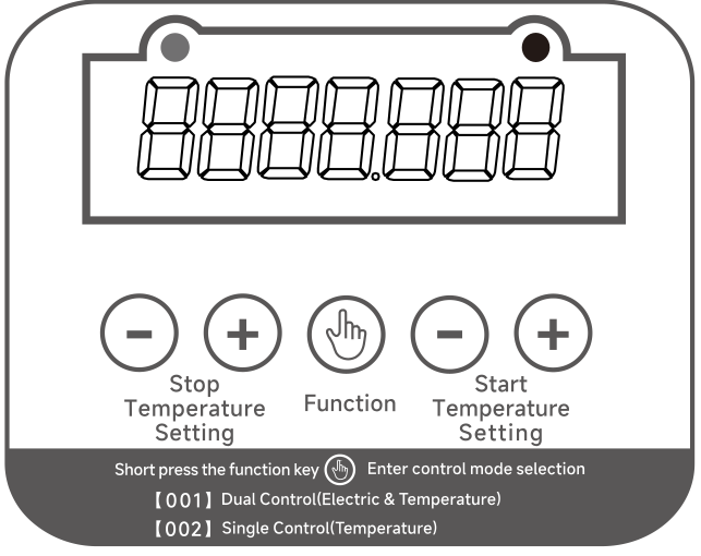
| Panel item | Function |
|---|---|
| Function | A short press selects the control mode. |
| Left - / + buttons | Stop Temperature Setting - adjusts the temperature at which operation stops. |
| Right - / + buttons | Start Temperature Setting - adjusts the temperature at which operation starts. |
| Green indicator | Power is on. |
| Red indicator | Misting is active. |
Set the misting start temperature higher than the stop temperature. Example settings: start 40 °C, stop 30 °C.
Mode 001 - temperature and current
Misting starts when the temperature exceeds the set start threshold and the current sensor detects that the air conditioner is running. When the temperature falls to the stop threshold, the system stops misting and enters standby.
Mode 002 - temperature only
Misting starts when the temperature exceeds the start threshold and stops when it falls to the stop threshold. This mode depends solely on the temperature measurement and can operate when the air conditioner is switched off.
Start-up
- 01Check the electrical connections and make sure the covers are closed. Open the water supply and check the connections for leaks.
- 02Switch on the P30J power supply. Select the operating mode and set the misting start and stop temperatures.
Checking operation
- 01Start the system in the selected mode. Check that misting starts automatically and that all five nozzles spray evenly and direct the mist correctly. Water must not flood electrical components or the surrounding area.
- 02Observe the panel readings, check the connections for leaks and check the temperature sensor position. The sensor must not be cooled directly by the mist; in mode 001, also check that the system detects the air conditioner running.
- 03When the stop temperature is reached, check that misting stops. Repeat the test and record the mode, settings and result.
If a leak occurs or the system does not start or stop misting correctly, stop the test, disconnect the power supply and shut off the water supply. Release the pressure before correcting the connections. Check the current sensor position and the connections.
Stopping
Disconnect the P30J power supply and shut off the water supply. Release the pressure before disconnecting the lines.
Maintenance
Before each maintenance procedure, check the device and its components for damage.
Cleaning the pre-filter and nozzles
- 01Every 3 months, remove the pre-filter mesh and clean off any deposits that could restrict flow.
- 02If a nozzle sprays poorly, unscrew it and check for debris inside. Clean the nozzle; do not drill out its opening.
- 03After reassembly, open the water supply and check for leaks, then switch on the power and check the spray and automatic stopping.
Frost protection
Insulate the inlet and outlet lines, pre-filter and accessories exposed to frost. Freezing may cause them to crack and leak water.
Troubleshooting
| Problem | Possible cause | Solution |
|---|---|---|
| Red indicator is on, but no water comes out of the nozzles | Blocked pre-filter mesh | Remove and clean the pre-filter mesh. |
| Red indicator is on, but no water comes out of the nozzles | No pressure in the inlet line | Check why the water supply has been cut off and restore it. |
| Red indicator is on, but no water comes out of the nozzles | Blocked nozzle | Unscrew the nozzle and remove the debris. |
| Leak at a water line connection | Excessive pressure | If the inlet pressure exceeds 8 bar, reduce it to 2–8 bar. |
| Leak at a water line connection | Incorrectly assembled connection | Check the seals and reassemble the connection. |
| Poor spray | Blocked pre-filter mesh | Remove and clean the pre-filter mesh. |
| Poor spray | Inlet pressure below 2 bar | Install an additional booster pump. The pressure must not exceed 8 bar. |
| Continuous misting | Incorrectly installed temperature sensor | Place the temperature sensor on the outdoor unit coil fins, away from the direct water spray. |
| Continuous misting | Stop temperature too low | Reset the stop temperature. Recommended setting: 30 °C. |
| Device does not start | Incorrectly installed temperature sensor | Place the temperature sensor on the outdoor unit coil fins, away from the direct water spray. |
| Device does not start | Start temperature too high; unit temperature has not reached the threshold | Reset the start temperature. Recommended setting: 40 °C. |
Waste electrical and electronic equipment
- 01The crossed-out bin symbol means that the device must not be disposed of with other waste at the end of its life.
Under applicable regulations on waste electrical and electronic equipment, products marked with the separate collection symbol must not be disposed of with other municipal waste. Due to their hazardous substance content, electronic products that are not collected separately may be harmful to the environment and human health. Proper separate collection of waste electrical and electronic equipment prevents adverse effects on the environment.
By taking waste equipment to a collection point, the user contributes to its reuse, recycling and recovery.
Recycling - one method of protecting the environment. The process of recovering substances from waste that can be reused as raw materials.
Waste recovery - the use of waste that has lost its useful value, such as plastics, paper and cardboard, as secondary raw materials; the term is also commonly used to mean destruction.
Information about the waste electrical and electronic equipment collection system
- ■Waste electrical and electronic equipment must not be disposed of with other waste.
- ■The collection of incomplete electrical and electronic equipment and parts from waste equipment is prohibited.
- ■A distributor delivering equipment intended for households to a purchaser is obliged to collect waste household equipment free of charge at the place of delivery, provided that the waste equipment is of the same type and performs the same function as the equipment delivered.
- ■The user may hand over waste equipment to a waste equipment collector, a treatment facility or a municipal waste collector operating in the municipality.
- ■Information about collection points is available on the BIP websites of regional, city and municipal authorities.
Service and documents
Before submitting a service request, prepare:
- ■Model - shown on the device rating plate and the invoice.
- ■Serial number - if absent, provide the production number (e.g. 11/2025), usually found on the underside of the device.
- ■Proof of purchase - an invoice or receipt from an authorised distributor.
- ■Description of the fault - what is happening, when it started and under what conditions.
Submit a service request at wipcool.pl/serwis. You will also find the warranty terms there.