
 Distribution PL · 4REF
Wipcool MDG-2K user manual
Read the entire manual before first use. Keep it for as long as you use the device.
Wipcool MDG-2K user manual
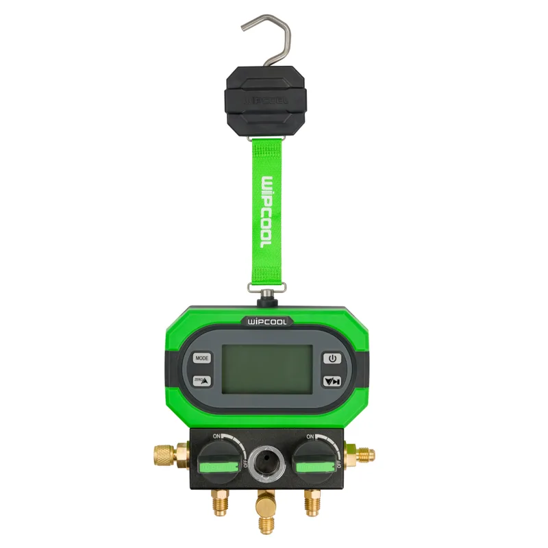
The MDG-2K is a digital manifold for measuring pressure and displaying saturation temperatures on the low and high sides.
The user manual is an integral part of the product. Read this manual carefully and follow all instructions strictly.
General information
Wipcool products are designed for professional use by qualified air conditioning and refrigeration technicians. As the manufacturer, Wipcool stipulates that our equipment should be operated only by people with appropriate qualifications and training.
- ■Observe all local safety regulations and general safety standards when using the Wipcool MDG-2K Digital Manifold.
- ■Keep the user manual near the device so that personnel can access it easily at all times.
- ■Before use, qualified personnel should read the user manual carefully and understand all the instructions it contains.
- ■The manufacturer accepts no liability for any damage resulting from improper use, failure to follow the user manual, lack of personnel qualifications or any unauthorised modifications to the device.
- ■The general terms of sale contained in the sales documents apply.
Symbols and conventions
Signs and markings used on the device and in the manual:
- 01
 Warning - read the text in the box next to the symbol.
- 02
 Warning of low temperature and frostbite caused by contact with refrigerant.
- 03
 Tip - practical advice on use.
- 04
 Before starting work, read all safety and installation instructions carefully.
- 05
 Indicates that the product meets the health, safety and environmental standards applicable in the European Union.
- 06RoHSThe product meets the requirements for restricting the use of hazardous substances.
- 07
 Do not dispose of the device with household waste.
LP / HP indicates the low / high side. PT is the mode for measuring pressure and displaying saturation temperatures, VAC - the mode for approximate vacuum measurement, and SET - the device settings.
Safety information
- ■Protect the manifold from harmful or corrosive substances.
- ■Do not release refrigerant into the atmosphere. Recover residual refrigerant from the hoses and manifold using a refrigerant recovery machine.
- ■Do not point the connections towards your body. Residual refrigerant can cause injury.
- ■If refrigerant gets into your eyes, immediately rinse them with plenty of water and contact a doctor.
Technical specifications
Device diagram
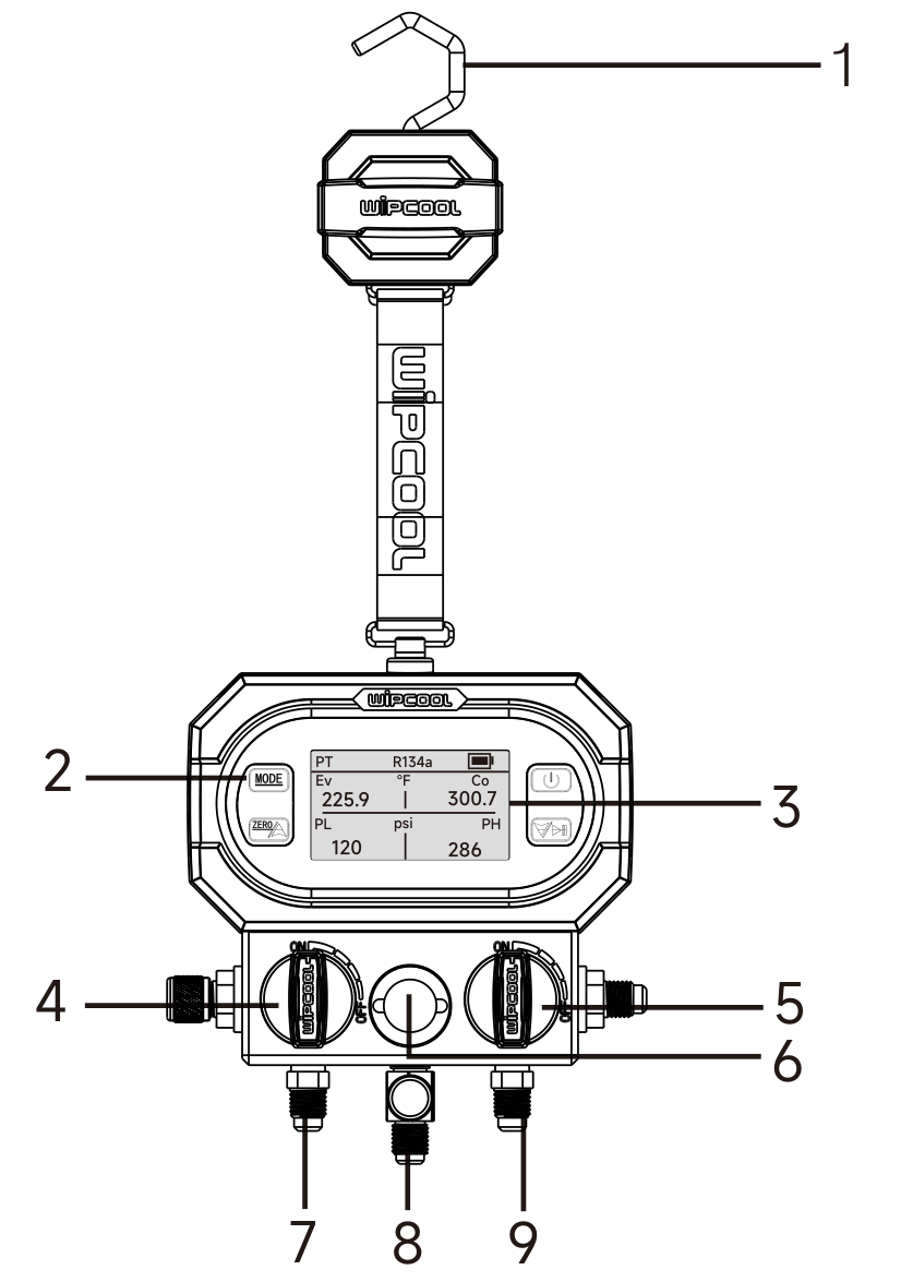
| No. | Component |
|---|---|
| 1 | Hook |
| 2 | Control buttons |
| 3 | LCD display |
| 4 | Low-side valve knob |
| 5 | High-side valve knob |
| 6 | Sight glass |
| 7 | Low-side hose connection |
| 8 | Centre connection |
| 9 | High-side hose connection |
Contents
After unpacking, check that the set is complete and in good condition. Report any missing or damaged items to the seller.
| Item | Quantity |
|---|---|
| MDG-2K manifold | 1 |
| Charging hoses: red, yellow and blue | 3 (1 of each colour) |
| 5/16" - 1/4" adapters | 2 |
| User manual | 1 |
Transport and storage
- ■Transport the device in its original packaging.
- ■Store in a dry place, away from direct sunlight and sources of heat.
Button functions and configuration
- 01
 PowerPress and hold to turn the device on or off.
- 02
 MODEPress and hold to enter or exit the SET settings. In the settings, press briefly to move to the next item. Outside the settings, press briefly to enter VAC mode.
- 03
 ZERO / up arrowPress and hold to zero the pressure sensor. Press briefly to change the refrigerant or a value in the settings.
- 04
 START/PAUSE / down arrowPress briefly to change the refrigerant or a value in the settings.
SET settings
- 01With the device switched on, press and hold MODE until SET appears in the top left corner of the screen.
- 02Press MODE briefly to move to the desired item. Change the value using the ZERO or START/PAUSE button.
- 03Press and hold MODE to exit the settings.
| Item | Available setting |
|---|---|
| PRESS | Pressure unit: bar, psi, kg/cm², kPa, MPa or inHg. |
| VAC | Vacuum measurement unit. |
| TEMP | Temperature unit: °C or °F. |
| AUTO OFF | Automatic switch-off after 5, 15, 30 or 60 min. OFF disables this function. Default: 15 min. |
| LANG | Language selection. |
| TC | Temperature compensation: ON (enabled) or OFF (disabled). Default: ON. |
Connection
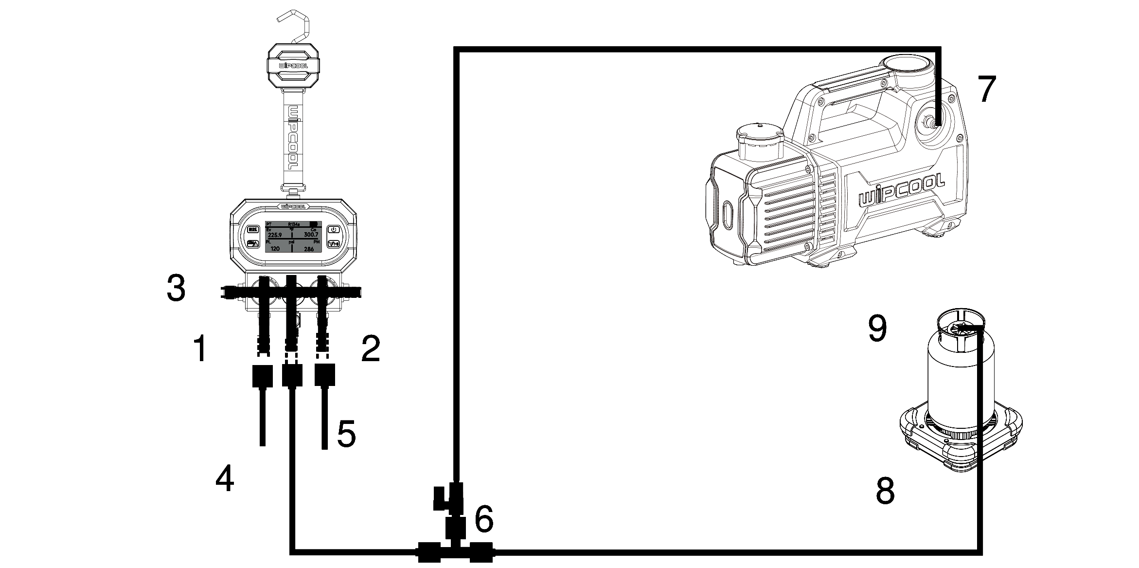
| No. on connection diagram | Description |
|---|---|
| 1 | Low-side valve |
| 2 | High-side valve |
| 3 | Bleed port |
| 4 | To the system low-side service port - blue hose |
| 5 | To the system high-side service port - red hose |
| 6 | Tee fitting with shut-off valve; the yellow hose leads to the centre connection of the manifold |
| 7 | Vacuum pump |
| 8 | Refrigerant charging scale |
| 9 | Refrigerant cylinder |
Preparing to measure in PT or VAC mode
During zeroing, the manifold must not be connected to a pressure source and its internal pressure must be equal to atmospheric pressure.
- 01Press and hold the power button to turn on the manifold.
- 02Before each measurement, press and hold ZERO to zero the pressure sensor.
Connecting for measurement in PT mode
- 01Close both manifold valves. Connect the blue hose to the low-side hose connection and the red hose to the high-side hose connection. Connect the blue hose to the system low-side service port and the red hose to the system high-side service port.
- 02In PT mode, press and hold ZERO and the START/PAUSE button simultaneously for 3 s. When the refrigerant name flashes, select the correct refrigerant using either button. The selection will be locked after 10 s.
Operation
Pressure and saturation temperature measurement - PT
- 01After connecting the manifold and selecting the refrigerant, start the system under test.
- 02In PT mode, read the pressures and the evaporating and condensing saturation temperatures. The readings change in real time.
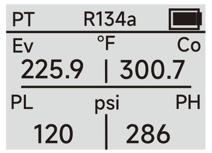
Vacuum measurement - VAC
- 01Close both manifold valves. Connect the red hose to the high-side hose connection (item 9 in figure 1) and to the system service port. Connect the centre connection (item 8 in figure 1) to the vacuum pump using the yellow hose, as shown in the connection diagram.
- 02Open the high-side valve (item 5 in figure 1). Leave the low-side valve (item 4 in figure 1) closed.
- 03Press MODE until VAC appears in the top left corner of the screen, then turn on the vacuum pump.
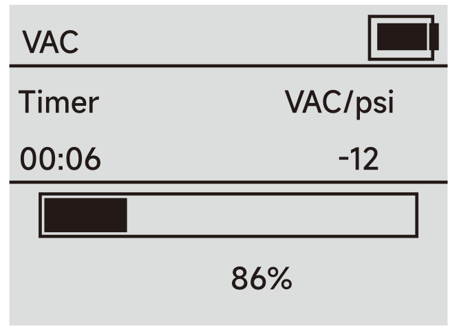
- 04Read the current pressure, vacuum value and time elapsed since entering VAC mode. When the pressure reading is below 0, the vacuum value will appear. Otherwise, dashes will be displayed.
- 05Once the required vacuum has been reached, close the high-side valve, then turn off the vacuum pump.
Maintenance
Hose inspection
Before each use, check the condition of the hoses and replace them if damaged.
Cleaning
Clean the housing with a damp cloth; you may use a mild detergent. Do not use strong alkaline or acidic detergents, corrosive agents or solvents. Clean the threaded connections of the charging hoses with a damp cloth; remove grease and other deposits.
Valve cleaning
Open the valve and blow it through with compressed air.
Troubleshooting
Dashes in the saturation temperature field indicate that the permitted saturation temperature range has been exceeded.
| Problem | Possible cause | Solution |
|---|---|---|
| The device switches off automatically | AUTO OFF function enabled | Select OFF in the AUTO OFF settings. |
| -OL- appears in the pressure field | Pressure is outside the permitted range | Stop the measurement. Use the manifold only within the range of -1–55 bar. |
Waste electrical and electronic equipment
- 01The crossed-out bin symbol means that the device must not be disposed of with other waste at the end of its life.
Under applicable regulations on waste electrical and electronic equipment, products marked with the separate collection symbol must not be disposed of with other municipal waste. Because they contain harmful substances, electronic products that are not sorted separately can be hazardous to the environment and human health. Proper separate collection of waste electrical and electronic equipment prevents negative effects on the environment.
By taking waste equipment to a collection point, the user contributes to its reuse, recycling and recovery.
Recycling - a method of protecting the environment. The process of recovering substances from waste that can be reused as raw materials.
Waste recovery - the use (commonly also the destruction) of waste that has lost its useful value, such as plastics, paper and cardboard, as secondary raw materials.
Information on the waste electrical and electronic equipment collection system
- ■Waste electrical and electronic equipment must not be disposed of with other waste.
- ■Collection of incomplete electrical and electronic equipment and parts from waste equipment is prohibited.
- ■A distributor delivering equipment intended for households to a purchaser must collect waste household equipment free of charge at the place of delivery, provided that the waste equipment is of the same type and performs the same function as the equipment delivered.
- ■The user may hand over waste equipment to a waste equipment collector, a treatment facility or a municipal waste collector in the municipality.
- ■Information on collection points is available on the BIP public information websites of regional, city and municipal authorities.
Batteries and rechargeable batteries
- 01The crossed-out bin symbol on a battery or rechargeable battery means that it must be collected separately from other waste at the end of its life. It must not be disposed of with municipal waste.
- ■Take used batteries and rechargeable batteries to a collection point. If possible, remove them from the device before handing it in for collection.
- ■Substances contained in batteries can harm the environment and health, especially if a battery is damaged or leaking. Separate collection allows them to be processed safely and raw materials to be recovered.
- ■The Cd or Pb marking below the bin symbol means that the battery contains more than 0.002% cadmium or more than 0.004% lead.
Service and documents
Before submitting a service request, prepare:
- ■Model - found on the device nameplate and on the invoice.
- ■Serial number - if there is none, provide the production number (e.g. 11/2025), usually found on the underside of the device.
- ■Proof of purchase - an invoice or receipt from an authorised distributor.
- ■Description of the fault - what is happening, when it started and under what conditions.
You can submit a service request at wipcool.pl/serwis. The warranty terms are also available there.