
 Distribution PL · 4REF
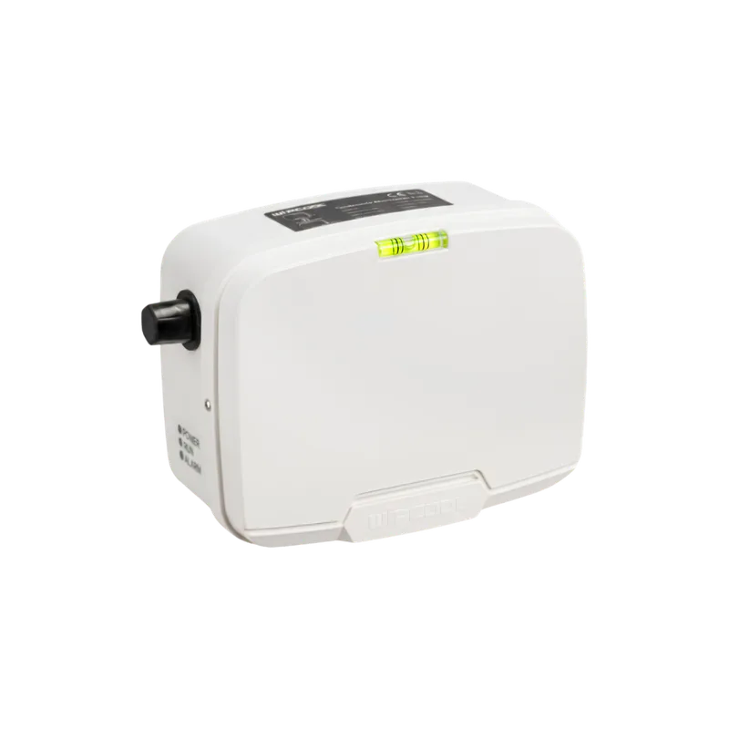
Wipcool P08J/P15J user manual
Wipcool P08J and P15J condensate atomisers spray condensate from air conditioners as a fine mist, reducing water dripping from the air conditioning unit.
The user manual is an integral part of the product. Please read this manual carefully and follow all instructions closely.
General information
Wipcool products are designed for professional use by qualified air conditioning and refrigeration engineers. As the manufacturer, Wipcool specifies that our devices should only be operated by suitably qualified and trained personnel.
- ■Observe all local safety regulations and general safety standards when using the Wipcool P08J/P15J condensate atomiser.
- ■Keep the user manual near the device so that personnel can access it easily at any time.
- ■Before use, qualified personnel should read the user manual carefully and understand all the instructions it contains.
- ■The manufacturer accepts no liability for any damage resulting from improper use, failure to follow the user manual, unqualified personnel or any unauthorised modifications to the device.
- ■The general terms of sale contained in the sales documents apply.
Symbols and conventions
Signs and markings used on the device and in the manual:
- 01
 Dangerous voltage - risk of electric shock.
- 02
 Notice - risk of damage to the device or an incorrect operating result.
- 03
 Indicates that the product meets the health, safety and environmental standards applicable in the European Union.
- 04RoHSThe product meets the requirements for restricting the use of hazardous substances.
- 05
 Do not dispose of the device with household waste.
Safety information
Only qualified personnel may install, connect and maintain the device.
- ■Do not use the device if the power cable, signal cable, housing, probes, hoses, connectors or nozzles are damaged.
- ■Do not use the atomiser in potentially explosive areas or near flammable materials.
- ■Use the device only for air conditioning condensate. Do not use it for hot water, chemically aggressive liquids, flammable liquids or contaminated process water.
- ■Use the device at an ambient temperature of 0–50 °C.
- ■If the device signals an alarm, runs continuously, does not spray water or operates abnormally, check the installation in accordance with the ‘TROUBLESHOOTING’ section.
Technical specifications
| Parameter | P08J | P15J |
|---|---|---|
| Power supply | 230 V~ / 50–60 Hz | 230 V~ / 50–60 Hz |
| Maximum flow rate with two nozzles | 8 l/h | 10 l/h |
| Operating pressure | 1.5 bar | 3 bar |
| Power consumption | max. 15 W | 25 W |
| Tank capacity | 35 ml | 35 ml |
| Maximum air conditioner cooling capacity | 6.5 kW | 8.8 kW |
| Noise level | 21 dB(A) | 40–45 dB(A) at a distance of 1 m |
| Ambient operating temperature | 0–50 °C | 0–50 °C |
| Protection class | II | II |
| Device weight | 1.2 kg | 1.2 kg |
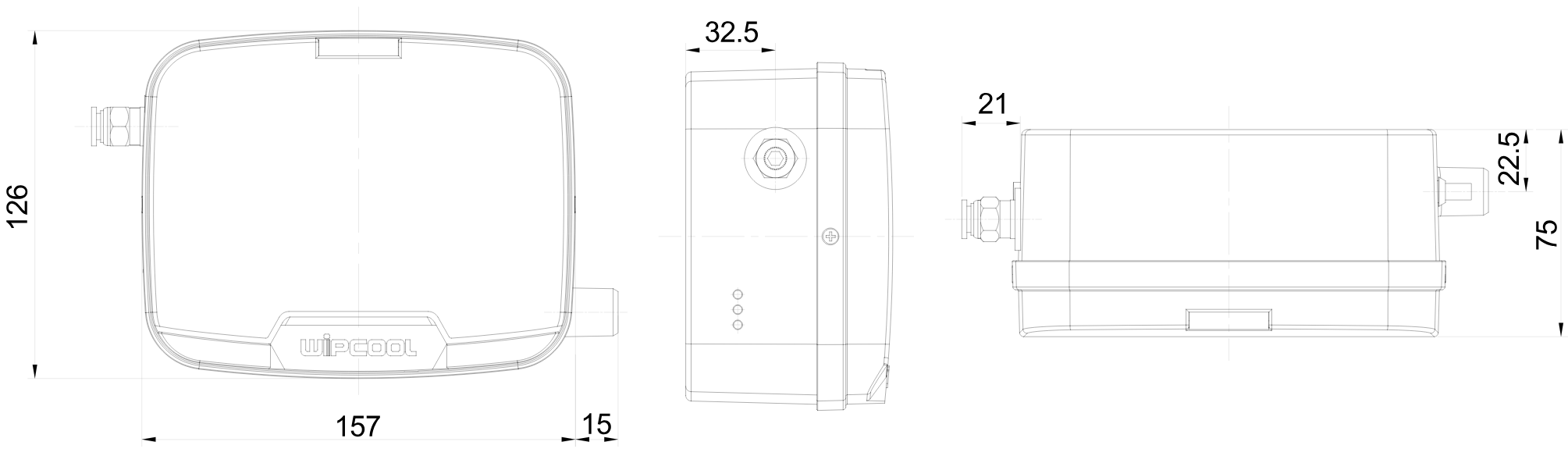
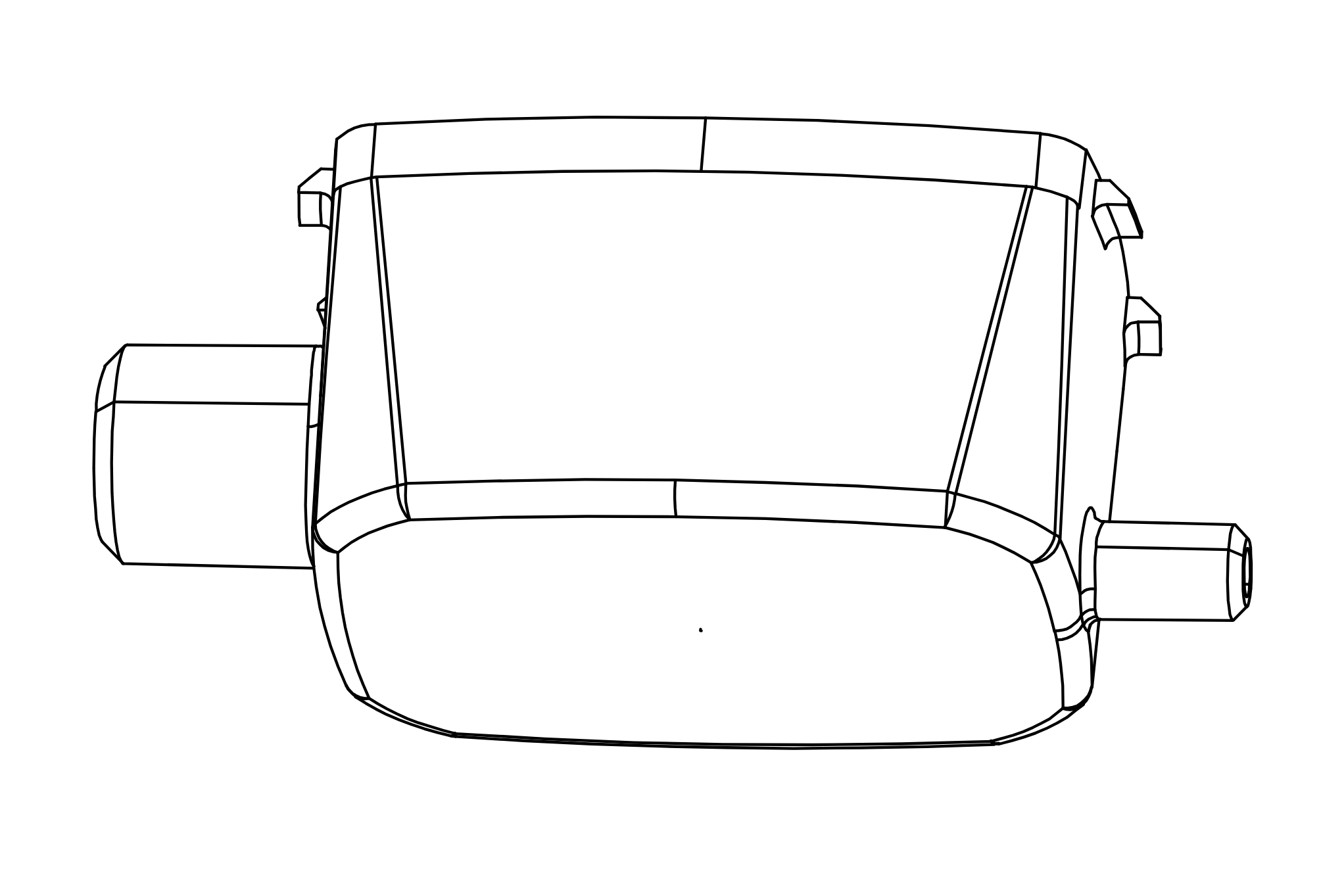
| Device dimensions (L × W × H) | 157 × 75 × 126 mm | 157 × 75 × 126 mm |
| Outlet hose diameter | Ø8 mm | Ø8 mm |
P15J with external tank: max. suction lift 1.5 m; suction hose 1.5 m; signal cable 1.5 m.
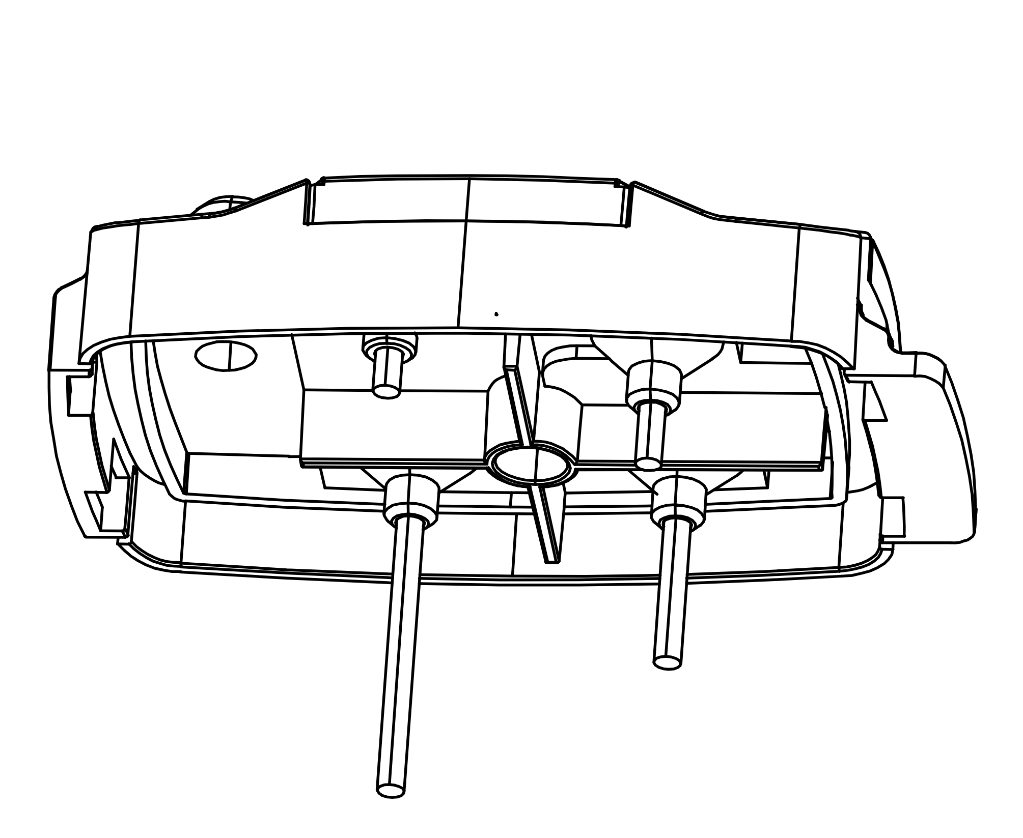
Device diagram
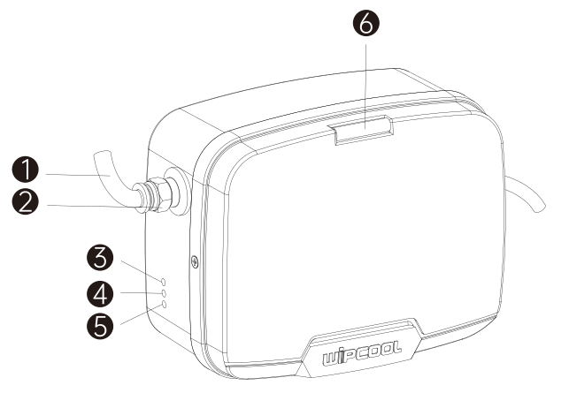
| No. | Name |
|---|---|
| 1 | Ø8 mm outlet hose |
| 2 | Ø8 mm quick-release coupling |
| 3 | Power indicator |
| 4 | Operating indicator |
| 5 | Alarm indicator |
| 6 | Spirit level |
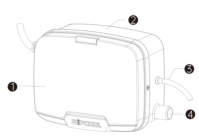
| No. | Name |
|---|---|
| 1 | Front housing |
| 2 | Rear housing |
| 3 | Power cable |
| 4 | Inlet connection |
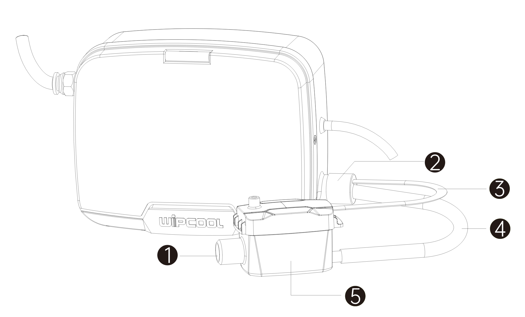
| No. | Name |
|---|---|
| 1 | Inlet connection |
| 2 | Rubber sleeve |
| 3 | 1.5 m signal cable |
| 4 | 1.5 m suction hose |
| 5 | Tank |
Atomiser dimensions
Contents
After unpacking, check that the kit is complete and in good condition. Report any missing or damaged items to the seller.
P08J
- ■Condensate atomiser.
- ■Two spray nozzles.
- ■Tee fitting.
- ■Ø8 mm outlet hose, 3 m long.
- ■Rubber connector.
- ■Two 100 × 3 mm cable ties.
- ■Mounting plate.
- ■Two wall plugs and two screws.
- ■Air vent and plugs.
- ■User manual.
P08J may have a Y-fitting or a T-fitting with a 90° elbow and a metal support bar. Use the components supplied in the kit.
P15J
- ■Condensate atomiser.
- ■Metal support bar with clips for mounting the nozzles.
- ■Ø8 mm polyamide outlet hose and Ø8 mm suction hose, 1.5 m long.
- ■T-fitting and 90° elbow.
- ■Two metal spray nozzles and two condensate hose connectors.
- ■Rubber connector, 6 mm reducer, rubber sleeve and cable ties.
- ■Adhesive hook-and-loop pad for mounting the tank, rubber vibration damper and mounting plate.
- ■Two screws and two wall plugs.
- ■Air vent and plugs.
- ■User manual.
Transport and storage
Transport
- ■Transport the device in its original packaging or protect it against mechanical damage. Avoid impacts, severe shocks and excessive vibration.
- ■Protect the device and accessories from dust, dirt and extreme temperatures.
- ■Do not kink, crush or strain the hoses, cables or nozzles. Secure the packages against movement.
Storage and winter shutdown
- ■Before storage, disconnect the power supply, drain the water from the device and clean it.
- ■Store the atomiser in a stable position without placing loads on the housing or connections. Store the accessories with the device.
- ■Avoid locations exposed to frost, flooding, dust and chemicals.
- ■For extended periods out of use, fit plugs to the inlet and outlet to protect them from dust and dirt.
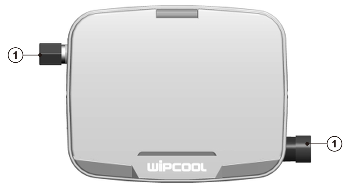
A device installed outdoors can remain in place during winter, but remove water from the tank and hoses before freezing conditions occur. Check the mounting and ensure that cables, hoses and connections are protected against damage. Before using the device again, check that the hoses are clear, the nozzles are in good condition and the probes operate correctly.
Application
Use the atomiser where conventional condensate drainage into the sewer, a drain or outside the building is difficult or undesirable.
Level sensor probes detect the water level in the tank. P08J operates with a tank inside the device. P15J can operate with an internal or external tank, depending on the installation location.
Installation
Condensate must flow into the P08J atomiser by gravity - route the pipe with a downward slope. For P15J, also route the air conditioner's drain pipe with a downward slope to the internal or external tank.
Positioning and mounting the device
- 01Choose a location that allows condensate to flow into the tank and water to be sprayed. Outdoors, install the atomiser below the air conditioner's outdoor unit, in a location protected against mechanical damage.
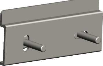
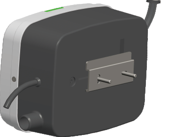
- 02Secure the mounting plate with screws and wall plugs. For P08J, drill Ø6 mm holes; for P15J, use the M4 × 20 self-tapping screws shown in figure 6.
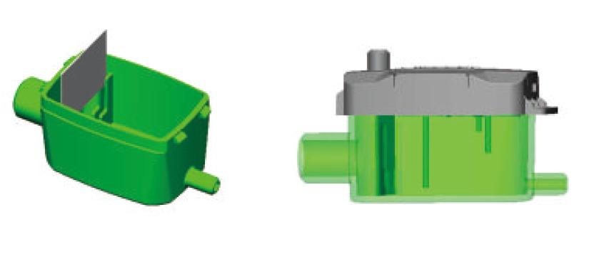
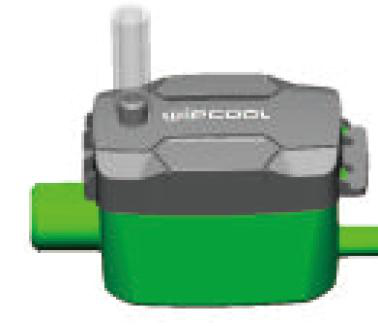
- 03When using the internal tank, check that the probes are positioned to the right of the tank filter and that the filter and tank cover are correctly seated. Connect the air vent.
- 04Hang the device on the plate, click it into place and check that it is secure. Level the body using the built-in spirit level.
- 05When using the internal tank, connect the air conditioner's drain pipe to the inlet connection (figure 2, item 4). Connect the Ø8 mm outlet hose to the atomiser's quick-release coupling (figure 1, item 2). Check the connections for leaks.
P15J - installing the tank outside the device
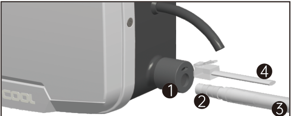
- 01Remove the front housing. Connect the rubber sleeve, condensate hose connector and suction hose as shown in figure 10.
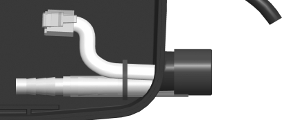
- 02Feed the suction hose and signal cable into the body. Secure them with a cable tie at the point shown in figure 11.
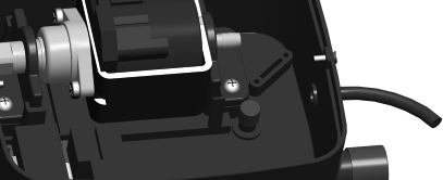
- 03Plug the overflow opening indicated in figure 12.
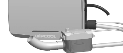
- 04Connect the air conditioner's drain pipe to the external tank (figure 13). Level the tank and connect the air vent.
- 05Check the connections for leaks and check the routing of the hoses and cables, then refit the front housing.
Installing the nozzles
- 01Choose a location on the outdoor unit for mounting the nozzles.
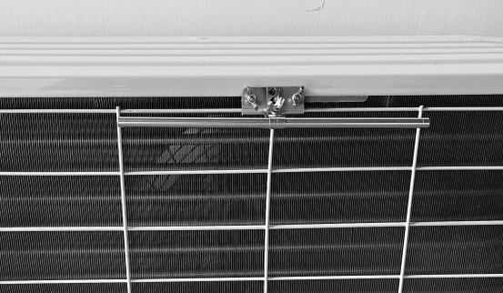
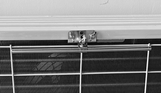
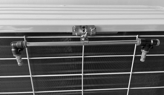
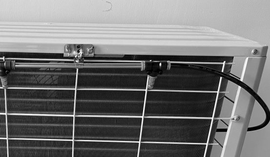
- 02For P15J and P08J with a metal support bar, secure the support bar with clips, then fit both nozzles into the clips (figures 15 and 16). For P08J without a metal support bar, secure the nozzles in the chosen location.
- 03Connect the outlet hose to the T-fitting or Y-fitting supplied with the kit and connect the nozzles. Set the spray direction.
- 04Check all connections. The hoses must not be kinked, crushed or blocked, and their routing must not restrict the flow.
Connection
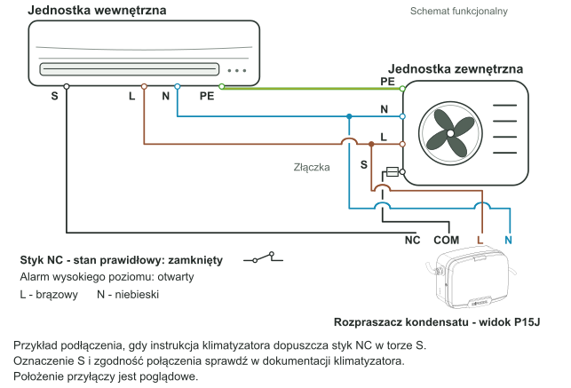
Only interrupt the S signal cable between the indoor and outdoor units (figure 18) and supply power to the atomiser from the outdoor unit if the air conditioner's manual permits it.
- 01Connect L - the brown wire - to the live conductor and N - the blue wire - to the neutral conductor.
- 02Connect the NC signal cable (normally closed circuit) to the air conditioner's condensate level protection circuit in accordance with its documentation. The alarm circuit must stop the air conditioner if there is a problem with condensate drainage. The atomiser must remain powered so that it can continue to remove water.
- 03Check the connections before switching on the power supply.
Operation
Test after installation
- 01Switch on the power supply and check that the power indicator (yellow) is lit.
- 02Pour water into the tank until the pump starts.
- 03Check that both nozzles spray. The device should operate steadily, without leaks, excessive vibration or unusual noises.
- 04Check that the pump stops automatically when the water level drops, and check again that the tank, hoses, cables and nozzles are secure.
Automatic operation and indicators
| Indicator | Meaning |
|---|---|
| Power indicator (yellow) | The power supply is on. |
| Operating indicator (green) | The pump is running after the start level has been reached. |
| Alarm indicator (red) and audible alarm | The water has reached the alarm level; the buzzer sounds for 3 min. |
The pump stops automatically when the water level drops.
When the signal circuit is connected, the alarm stops the air conditioner. Once normal operation is restored, the alarm indicator goes out and the air conditioner can operate again.
If the alarm persists or the device operates incorrectly, carry out the checks in the ‘TROUBLESHOOTING’ section.
Maintenance
General recommendations
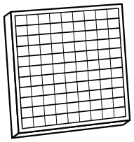
Clean the tank and filter every 3 months, or more often if the device is exposed to greater amounts of dirt. Also inspect the hoses, cables, connectors, probes and nozzles.
Do not use solvents, corrosive agents, alcohol, petrol or sharp tools. Do not change the position of the probes or damage their connections.
Maintenance procedure
- 01Check that the hoses, connectors, tee fitting and nozzles are clear. Remove any kinks and blockages.
- 02Clean deposits from the tank and probe surfaces.
- 03Remove and clean the tank filter, then refit it in the correct position.
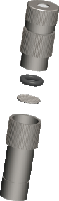
- 04Remove and clean the nozzle filter. Check that both nozzles are clear and refit the filters.
- 05Check that the tank, hoses, cables and connections are securely fitted.
- 06Perform the test according to steps 1–4 in the ‘Test after installation’ section.
Troubleshooting
| Problem | Possible cause | Solution |
|---|---|---|
| Device does not start | No power supply; power indicator is off | Check the power supply connection. |
| Device does not start | Loose connection; power indicator is lit | Check the electrical connections according to figure 18. |
| Device does not start | Incorrect voltage | Check that the voltage matches the rating plate. |
| Device does not start | Tank is not level or water level is incorrect | Level the tank and check the water level. |
| Device runs continuously | Device or tank is not level | Level the device and tank. |
| Device runs continuously | Deposits in the tank or dirty probes | Clean the tank and probes. |
| Device does not spray water | No gravity feed or blocked air conditioner drain pipe; for P15J, also a kinked or blocked suction hose | Remove blockages and route the air conditioner's drain pipe with a downward slope to the tank. For P15J, also check that the suction hose is clear. |
| Device does not spray water | Contaminated pump | Fill the tank and run the pump to flush out contaminants. If flushing does not help, do not restart the device. Arrange for repair by the service centre - submit a request at wipcool.pl/serwis. |
| Spray is weak | Blocked tank or nozzle filter | Clean the tank filter, hoses, nozzles and their filters. |
| Spray is weak | Kinked outlet hose or incorrectly installed tee fitting and nozzles | Check that the Ø8 mm outlet hose is clear and check the installation of the tee fitting and nozzles. |
| Device is louder than usual | Device, tank, hoses or cables are not securely mounted; vibration is being transmitted | Check that the body, plate, tank, hoses and cables are secure. Use vibration dampers if necessary. |
| Water is leaking | Leaking connection, incorrectly fitted hose or incorrectly positioned tank | Correct the installation of the hoses and connectors and the position of the tank. Use a cable tie if necessary. |
| Water is leaking | Damaged hose or connection | Replace the damaged component. |
| Alarm indicator is lit or audible alarm is sounding | Alarm level reached, dirty probes, blocked hoses, filter or nozzles | Check that the hoses, filter and nozzles are clear and clean the probes. |
| Alarm indicator is lit or audible alarm is sounding | Signal cable incorrectly connected | Check the signal cable connection according to figure 18. |
| Air conditioner switches off after the signal cable is connected | Incorrect connection or incompatibility with the air conditioner's circuit | Check the NC signal cable connection according to figure 18 and the air conditioner's documentation. |
If the problem persists, do not restart the device. Arrange for repair by the service centre - submit a request at wipcool.pl/serwis.
Waste electrical and electronic equipment
- 01The crossed-out wheeled bin symbol means that the device must not be disposed of with other waste at the end of its life.
Under the applicable regulations on waste electrical and electronic equipment, products marked with the separate collection symbol must not be disposed of with other municipal waste. Because they contain hazardous substances, electronic products that are not collected separately may pose a risk to the environment and human health. Proper separate collection of waste electrical and electronic equipment prevents adverse effects on the environment.
By taking waste equipment to a collection point, the user contributes to its reuse, recycling and recovery.
Recycling - one method of protecting the environment. The process of recovering substances from waste that can be reused as raw materials.
Waste recovery - the use (also commonly understood as destruction) of waste that has lost its useful value, such as plastics, paper and cardboard, as secondary raw materials.
Information on the waste electrical and electronic equipment collection system
- ■Waste electrical and electronic equipment must not be disposed of with other waste.
- ■The collection of incomplete electrical and electronic equipment and parts from waste equipment is prohibited.
- ■A distributor delivering equipment intended for households to a purchaser must collect waste equipment from households free of charge at the place of delivery, provided that the waste equipment is of the same type and performs the same function as the equipment delivered.
- ■The user may hand over waste equipment to a waste equipment collector, a treatment facility or a municipal waste collector operating in the municipality.
- ■Information on collection points is available on the Public Information Bulletin (BIP) websites of regional, city and municipal authorities.
Service and documents
Before submitting a service request, have the following ready:
- ■Model - shown on the equipment nameplate and on the invoice.
- ■Serial number - if there is none, provide the production number (e.g. 11/2025), usually found on the underside of the equipment.
- ■Proof of purchase - an invoice or receipt from an authorised distributor.
- ■Description of the fault - what is happening, since when and under what conditions.
Submit a service request at wipcool.pl/serwis. You will also find the warranty terms there.