
 Distribution PL · 4REF
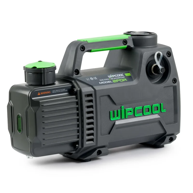
Wipcool 2F0R-2F5R user manual
Wipcool 2F0R, 2F1R, 2F1.5R, 2F2R, 2F3R, 2F4R and 2F5R vacuum pumps have a two-stage rotary vane design. They are used to create a vacuum in closed systems.
The user manual is an integral part of the product. Please read this manual carefully and follow all instructions closely.
General information
Wipcool products are designed for professional use by qualified air conditioning and refrigeration engineers. As the manufacturer, Wipcool stipulates that our equipment should only be operated by suitably qualified and trained personnel.
- ■Comply with all local safety regulations and general safety standards when using the Wipcool 2F0R-2F5R vacuum pump.
- ■Keep the user manual near the device so that personnel can access it easily at any time.
- ■Before use, qualified personnel should read the user manual carefully and understand all the instructions it contains.
- ■The manufacturer accepts no liability for any damage resulting from improper use, failure to follow the user manual, unqualified personnel or any unauthorised modifications to the device.
- ■The general terms of sale contained in the sales documents apply.
Symbols and conventions
Symbols and markings used on the device and in the manual:
- 01
 Warning - read the text in the box next to the symbol.
- 02
 Dangerous voltage - risk of electric shock.
- 03
 Warning of a fire or explosion hazard.
- 04
 Notice - risk of damage to the device or an incorrect operating result.
- 05
 Indicates that the product meets the health, safety and environmental standards applicable in the European Union.
- 06
 Do not dispose of the pump with household waste.
Safety information
Technical specifications
| Parameter | 2F0R | 2F1R | 2F1.5R | 2F2R |
|---|---|---|---|---|
| Max. flow rate [l/min] | 42 | 71 | 85 | 142 |
| Oil quantity [ml] | 280 | 280 | 480 | 450 |
| Device weight [kg] | 4.5 | 4.5 | 7.5 | 8.0 |
| Dimensions (L × W × H) [mm] | 309 × 113 × 198 | 309 × 113 × 198 | 339 × 130 × 225 | 339 × 130 × 225 |
| Connections | 1/4" SAE | 1/4" SAE | 1/4" and 3/8" SAE | 1/4" and 3/8" SAE |
| Parameter | 2F3R | 2F4R | 2F5R |
|---|---|---|---|
| Max. flow rate [l/min] | 198 | 255 | 312 |
| Oil quantity [ml] | 520 | 500 | 480 |
| Device weight [kg] | 10.0 | 10.5 | 11.0 |
| Dimensions (L × W × H) [mm] | 365 × 147 × 242 | 365 × 147 × 242 | 365 × 147 × 242 |
| Connections | 1/4" and 3/8" SAE | 1/4" and 3/8" SAE | 1/4" and 3/8" SAE |
Device diagram
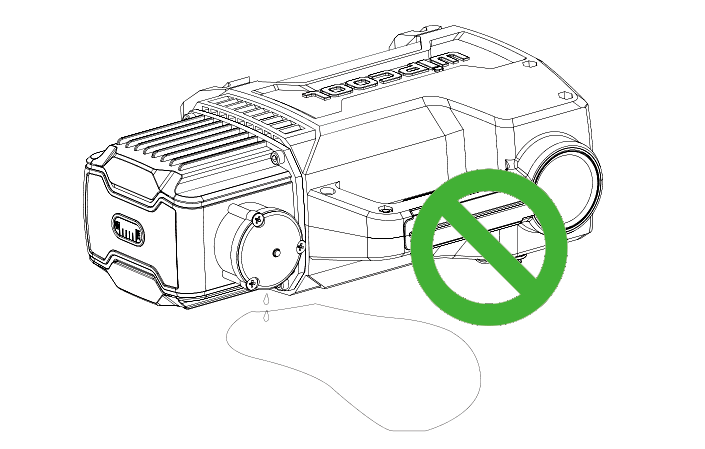
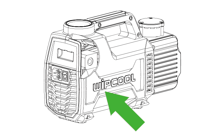
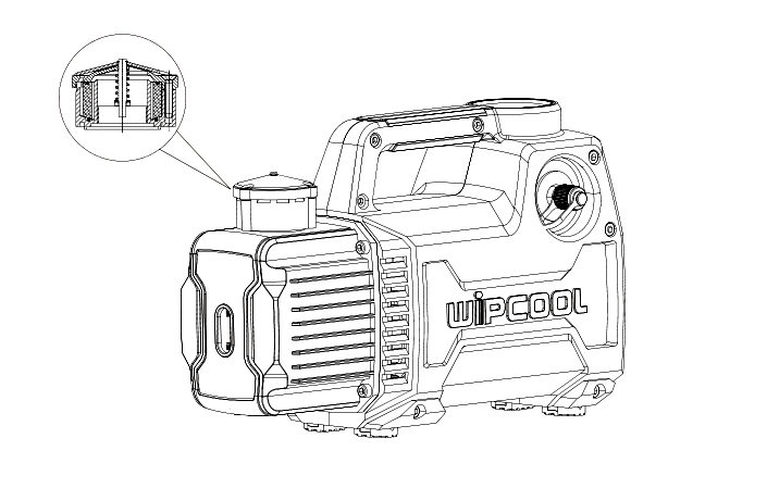
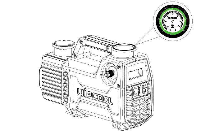
Pump parts
| Part | Function or location |
|---|---|
| Vacuum gauge | Indicates the vacuum; located on top of the pump (Figure 4). |
| Oil sight glass | Used to check the oil level. |
| Transport plug | Seals the oil filler opening during transport (Figure 6). |
| Oil filler cap | Fitted in place of the transport plug (Figure 7). |
| Drain plug | Located beneath the oil reservoir; used to drain the oil. |
| Vacuum hose connection | Used to connect the pump to the system (Figure 8). |
| Power switch | Used to start the pump (Figure 9). |
Dimensions
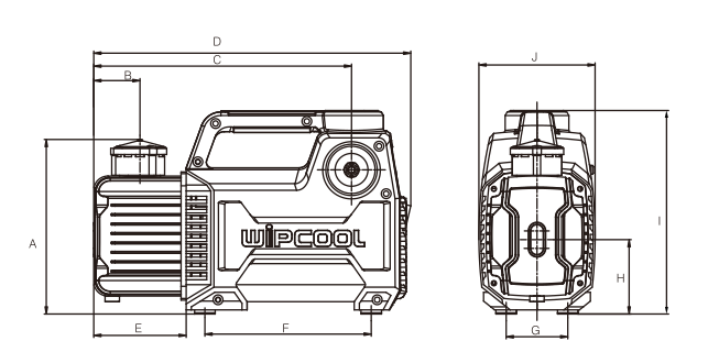
| DIMENSION [mm] | 2F0R, 2F1R | 2F1.5R, 2F2R | 2F3R, 2F4R, 2F5R |
|---|---|---|---|
| A | 175 | 195 | 211 |
| B | 45 | 45 | 50 |
| C | 250 | 280 | 300 |
| D | 309 | 339 | 365 |
| E | 90 | 110 | 115 |
| F | 162 | 165 | 190 |
| G | 60 | 70 | 70 |
| H | 73 | 87 | 97 |
| I | 200 | 225 | 242 |
| J | 115 | 130 | 147 |
Package contents
- ■Vacuum pump with transport plug.
- ■Oil filler cap.
A vacuum hose is required for operation. The pump requires vacuum pump oil.
Application
The pumps are used to evacuate refrigeration systems containing R12, R22, R134a, R410A and mildly flammable A2L refrigerants, such as R32 and R1234yf. They have a non-sparking design. The pumps can also be used in other high-vacuum systems, such as printing equipment and medical instruments, as well as for vacuum packaging, gas analysis and thermoplastic forming.
How to use
Pre-operation check
Check that the pump and accessories are complete and undamaged and that there are no oil leaks in the packaging. Report any transport damage or missing items to the seller.
Preparation and start-up
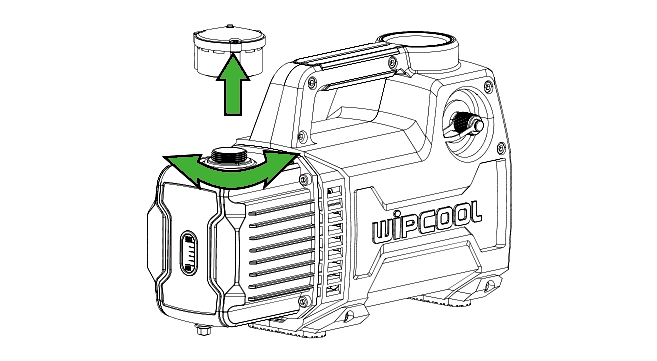
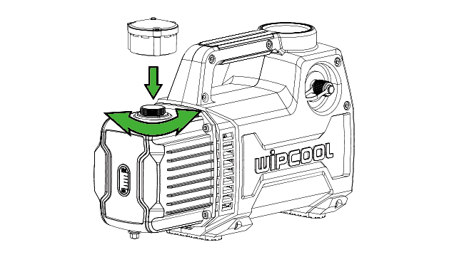
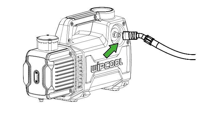
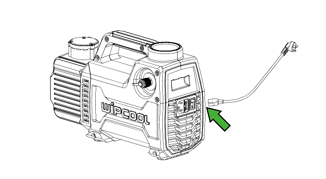
Maintenance
Checking the oil
Replace the oil if it is contaminated, brown, black, emulsified or foaming.
Changing the oil
1. Unscrew the drain plug beneath the oil reservoir and drain the oil, then tighten the plug.
Step 2
Unscrew the oil filler cap and slowly pour oil into the pump.
3. Connect the pump to the power supply, switch it on and observe the oil level. When it stabilises at the halfway point of the sight glass, tighten the oil filler cap.
4. Turn off the pump using the power switch.
Troubleshooting
| Problem | Possible cause | Solution |
|---|---|---|
| Pump does not reach the required vacuum | Insufficient oil | Top up the oil to the halfway point of the sight glass. |
| Pump does not reach the required vacuum | Emulsified or contaminated oil | Change the oil. |
| Pump does not reach the required vacuum | Blocked oil inlet or insufficient oil flow | Clean the oil inlet and filter screen. |
| Pump does not reach the required vacuum | Leak in the vacuum hose or reservoir | Check the vacuum hose and reservoir for leaks; repair any leak. |
| Pump does not reach the required vacuum | Pump unsuitable for the system | Check the size of the system and select a pump with a suitable flow rate. |
| Pump does not reach the required vacuum | Wear of parts after prolonged operation, increased clearance or an internal leak | You can replace the pump with a new one or have it repaired. Arrange for a service centre to repair it - submit a request at wipcool.pl/serwis. |
| Pump does not reach the required vacuum | Contaminated sealing surface on the oil filler cap | Check and clean the sealing surface on the oil filler cap. |
| Oil leak | Worn shaft seal | Arrange for a service centre to repair it - submit a request at wipcool.pl/serwis. |
| Oil leak | Loose or damaged oil reservoir connection | Arrange for a service centre to repair it - submit a request at wipcool.pl/serwis. |
| Difficult start-up | Oil temperature too low | Before connecting the pump to the system, switch it on with the inlet open and let it run until the oil warms up. |
| Difficult start-up | Motor or power supply problem | Check the power supply. Arrange for a service centre to repair it - submit a request at wipcool.pl/serwis. |
| Difficult start-up | Contamination inside the pump | Arrange for a service centre to repair it - submit a request at wipcool.pl/serwis. |
| Pump does not start or stops suddenly | Blown fuse | Check and replace the fuse. |
| Pump does not start or stops suddenly | Motor or power supply problem | Check the power supply. Arrange for a service centre to repair it - submit a request at wipcool.pl/serwis. |
Waste electrical and electronic equipment
- 01The crossed-out bin symbol means that the end-of-life device must not be disposed of with other waste.
Under applicable regulations on waste electrical and electronic equipment, products marked with the separate collection symbol must not be disposed of with other municipal waste. Because they contain harmful substances, electronic products that are not collected separately may be hazardous to the environment and human health. Proper separate collection of waste electrical and electronic equipment prevents adverse effects on the environment.
By taking end-of-life equipment to a collection point, the user contributes to its reuse, recycling and recovery.
Recycling - one method of protecting the environment. The process of recovering substances from waste that can be reused as raw materials.
Recovery - the use of waste that has lost its useful value, such as plastics, paper and cardboard, as secondary raw materials (also commonly used to mean destruction).
Information on the collection system for waste electrical and electronic equipment
- ■Waste electrical and electronic equipment must not be disposed of with other waste.
- ■The collection of incomplete electrical and electronic equipment and parts from waste equipment is prohibited.
- ■A distributor supplying equipment intended for households to a purchaser must collect waste equipment from households free of charge at the place of delivery, provided that the waste equipment is of the same type and performs the same function as the equipment supplied.
- ■The user may hand over waste equipment to a waste equipment collector, a treatment facility or a municipal waste collector operating in the municipality.
- ■Information on collection points is available on the BIP websites of regional marshal offices and city and municipal offices.
Service and documents
Before submitting a request, prepare:
- ■Model - shown on the device nameplate and on the invoice.
- ■Serial number - if there is none, provide the production number (e.g. 11/2025), usually found on the underside of the device.
- ■Proof of purchase - an invoice or receipt from an authorised distributor.
- ■Fault description - what is happening, when it started and under what conditions.
Submit a service request at wipcool.pl/serwis. The warranty terms are also available there.