
 Distribution PL · 4REF
Wipcool AIT500 user manual
Read the entire manual before first use. Keep it for as long as you use the device.
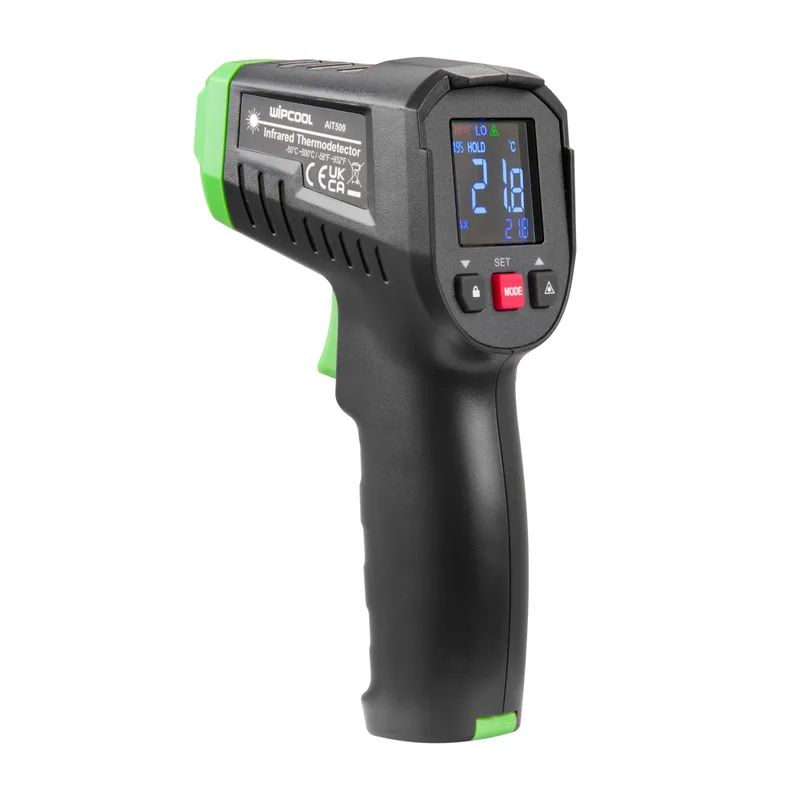
Wipcool AIT500 user manual
The Wipcool AIT500 infrared thermometer measures surface temperature without contact, based on the infrared energy emitted by the surface. The ratio of measurement distance to measurement spot diameter D:S is 12:1.
The user manual is an integral part of the product. Please read this manual carefully and follow all instructions closely.
General information
Wipcool products are designed for professional use by qualified air conditioning and refrigeration engineers. As the manufacturer, Wipcool specifies that our devices should be operated only by suitably qualified and trained persons.
- ■Observe all local safety regulations and general safety standards when using the Wipcool AIT500 infrared thermometer.
- ■Keep the user manual near the device so that personnel can easily access it at any time.
- ■Before use, qualified personnel should read the user manual carefully and understand all the instructions it contains.
- ■The manufacturer accepts no liability for any damage resulting from improper use, failure to follow the user manual, lack of personnel qualifications or any unauthorised modifications to the device.
- ■The general terms of sale contained in the sales documents apply.
Symbols and conventions
Symbols and markings used on the device and in the manual:
- 01
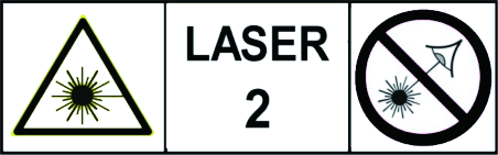 Laser radiation. Do not stare into the beam. Class 2 laser product.
- 02
 Warning of laser radiation.
- 03
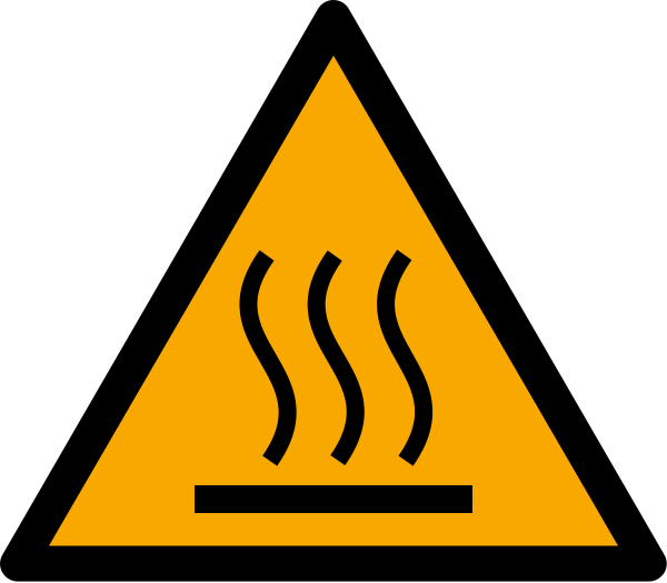 Hot surface - wait for it to cool before touching.
- 04
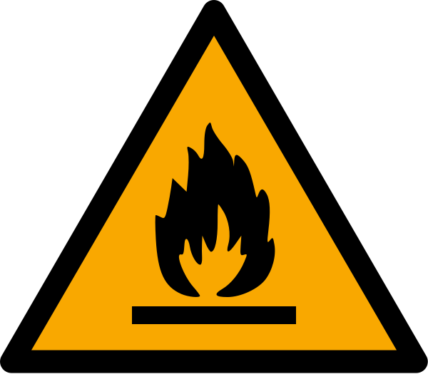 Warning of flammable materials and fire hazard.
- 05
 Notice - risk of damage to the device or an incorrect result.
- 06
 Indicates that the product meets the health, safety and environmental standards applicable in the European Union.
- 07
 Do not dispose of the infrared thermometer with household waste.
Safety information
Wavelength λ = 630–670 nm, power < 1 mW; EN 60825-1:2014.
General rules
- ■Do not disassemble or modify the infrared thermometer or the laser.
- ■Check the condition of the infrared thermometer before use. Do not use it if it is damaged, cracked or if any part of the plastic housing is missing.
- ■When the low battery indicator appears, replace the batteries to prevent incorrect measurements.
- ■Do not use the infrared thermometer in the presence of steam, dust or large temperature fluctuations, which may distort the result. Before use, leave the infrared thermometer at the measurement location for more than 30 min.
- ■Do not leave the infrared thermometer on or near hot objects.
Technical specifications
Device diagram
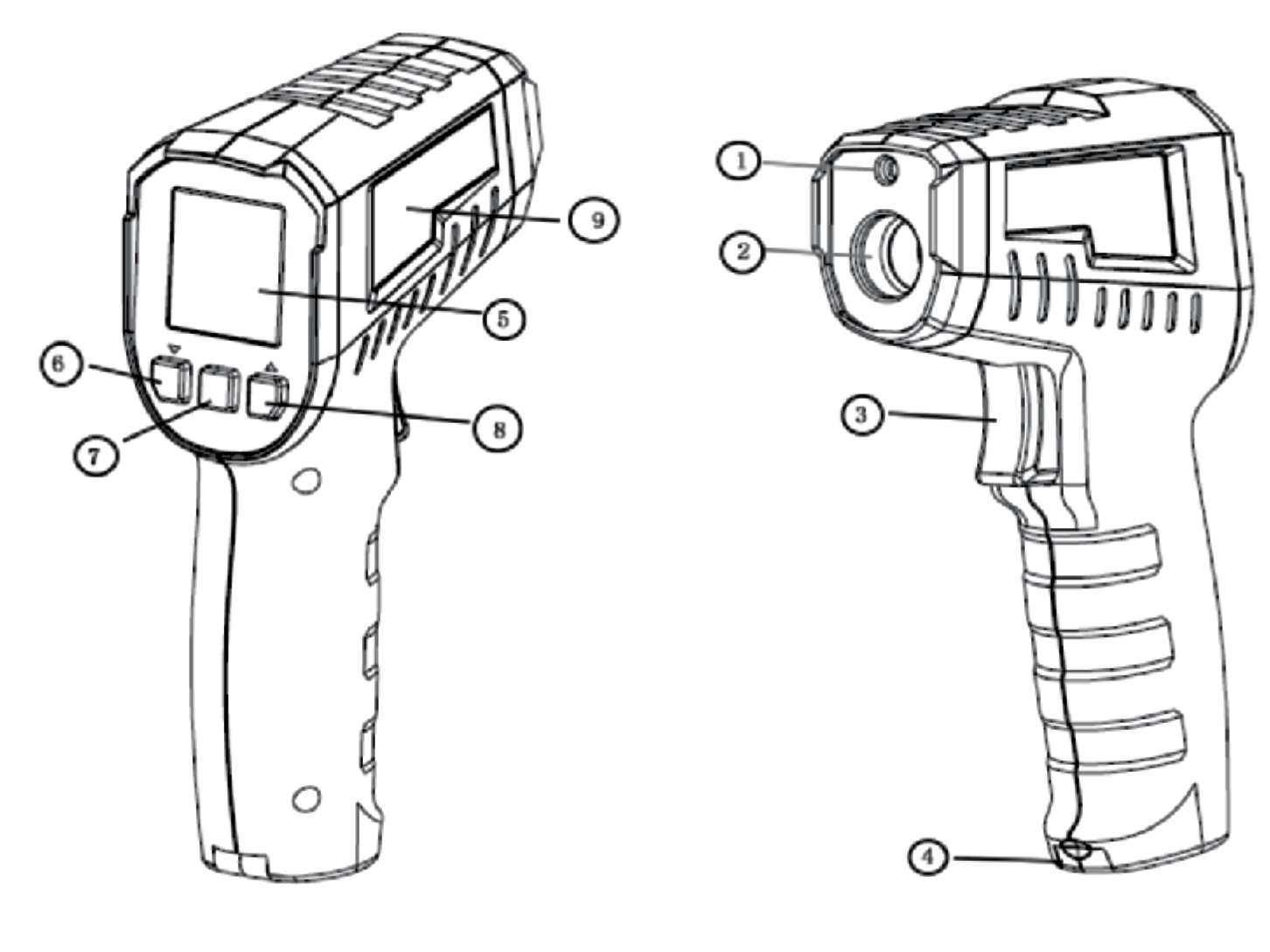
| No. | Name |
|---|---|
| 1 | Laser |
| 2 | Infrared receiving window |
| 3 | Trigger |
| 4 | Battery compartment cover |
| 5 | LCD display |
| 6 | LOCK button (▼) |
| 7 | MODE button |
| 8 | LASER button (▲) |
| 9 | Laser warning label |
Buttons
| Button | Function |
|---|---|
| LOCK (▼) | Measurement lock; decreases values in settings |
| MODE | Selects modes and settings |
| LASER (▲) | Switches the laser pointer on and off; increases values in settings |
Display
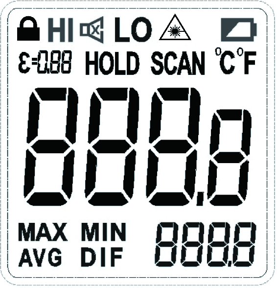
| Indicator | Meaning |
|---|---|
| Padlock | Locked measurement |
| Speaker | Buzzer |
| HOLD | Reading held |
| Battery | Low battery |
| ε | Emissivity |
| MAX / MIN / AVG / DIF | Result display mode in the secondary field |
| HI / LO | High / low temperature alarm |
| Laser symbol | Laser pointer on |
| SCAN | Temperature measurement |
| °C / °F | Temperature unit |
| Large digits | Main temperature field |
| Small digits at the bottom | Secondary temperature field |
Package contents
- ■AIT500 infrared thermometer.
- ■User manual.
After unpacking, check that the package is complete and in good condition.
Transport and storage
- ■Transport the infrared thermometer in its original packaging.
- ■Store the infrared thermometer in a dry place, away from direct sunlight and heat sources, at a temperature of -20 to +60 °C.
How to use
Before first use, insert the batteries as described in ‘Replacing the batteries’ (MAINTENANCE section).
Switching on
Briefly press the trigger (for less than 0.5 s) to switch on the infrared thermometer. The display will show the last result saved before the device was switched off. Use the MODE button to select a secondary result described in ‘MAX / MIN / AVG / DIF results’.
Automatic power-off
After 15 s of inactivity in HOLD mode, the infrared thermometer will automatically switch off and save the current result.
Manual measurement
Point the infrared thermometer at the surface and hold the trigger. A flashing SCAN indicates that measurement is in progress; the result on the LCD display is updated.
Locked measurement
Point the infrared thermometer at the surface to be measured and briefly press the LOCK button. A padlock will appear and SCAN will start flashing; the infrared thermometer will measure without the trigger being held.
You can also start a locked measurement with the infrared thermometer switched off: briefly press the LOCK button. Do not hold this button for more than 3 s.
Selecting the distance and field of view
The greater the distance D from the object, the greater the diameter S of the measurement spot. D:S = 12:1; the spot includes 95% of the energy. The object being measured should be larger than twice the spot diameter. The smaller the object, the closer you must position the infrared thermometer.
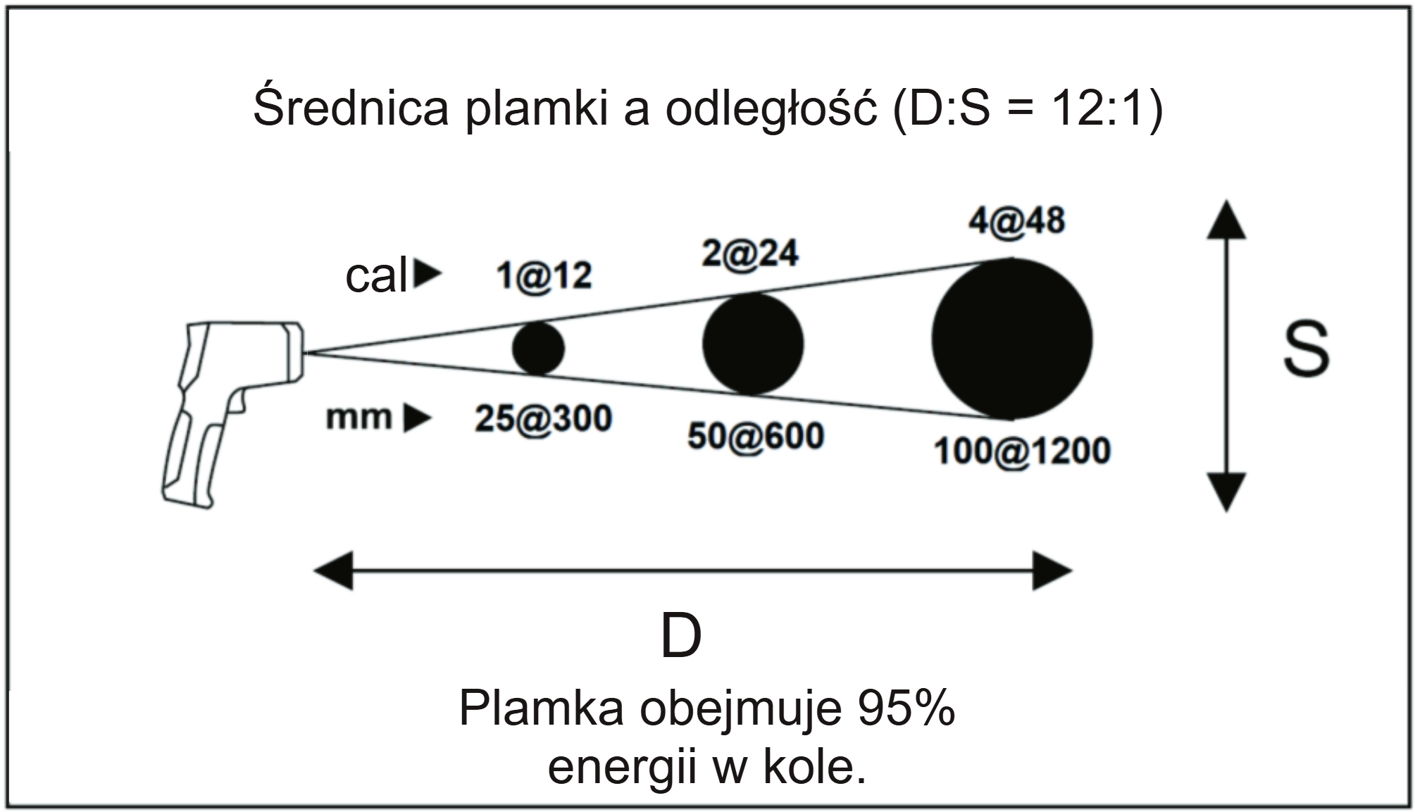
Example: for an object approximately 10 cm in diameter, use a spot of approximately 5 cm and a distance of approximately 60 cm.
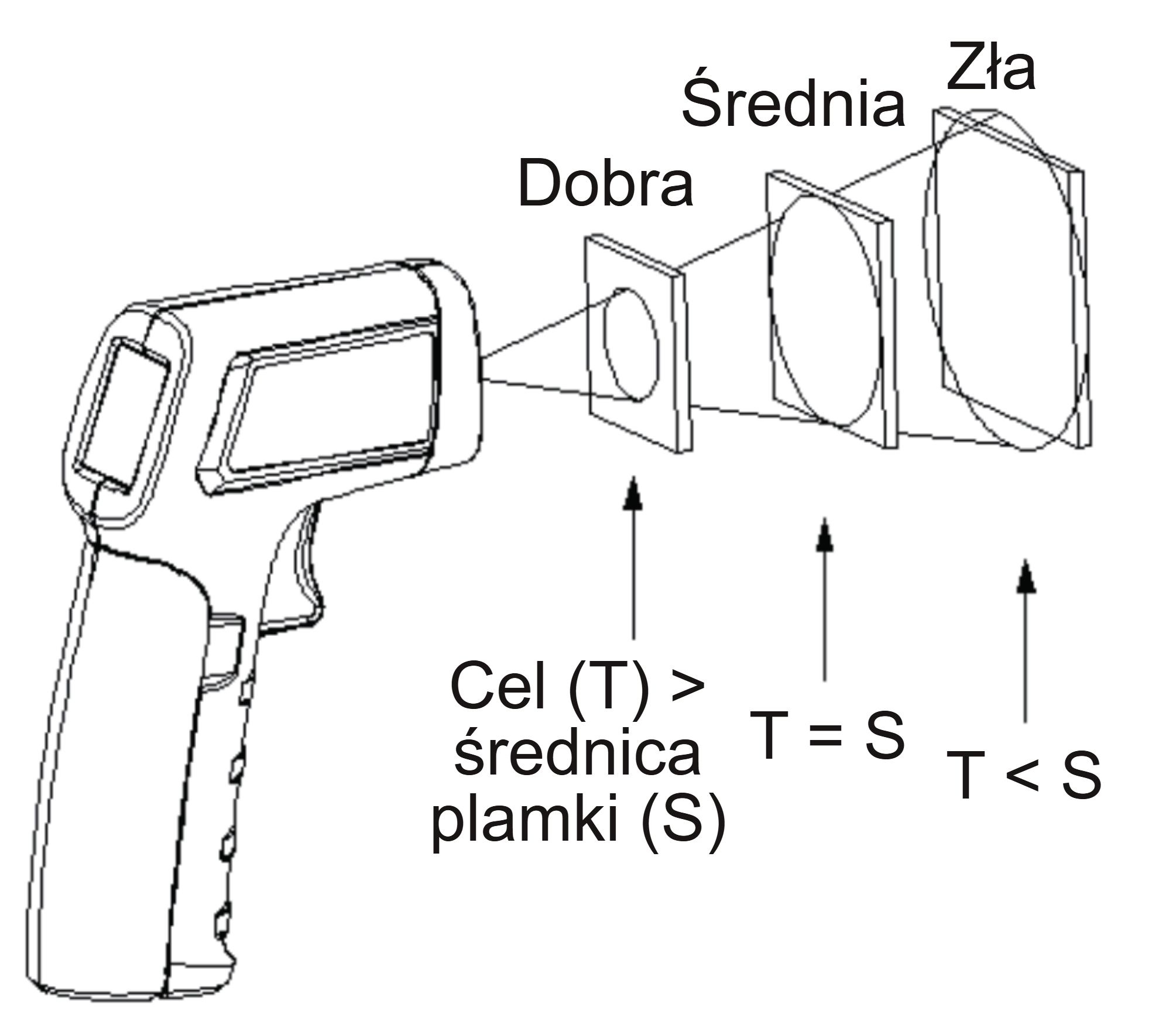
MAX / MIN / AVG / DIF results
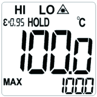
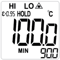
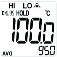
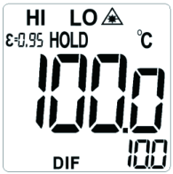
Briefly press the MODE button repeatedly to cycle through the modes MAX → MIN → AVG → DIF. The result for the selected mode appears in the secondary display field: MAX mode - highest temperature, MIN mode - lowest, AVG mode - average, and DIF mode - difference between the highest and lowest temperatures (MAX - MIN).
Laser pointer
Use the LASER button (no. 8 in figure 2) to switch the pointer on and off. When it is on, the laser symbol appears on the LCD display and the beam indicates the measurement location. Before switching it on, observe the laser safety rules described in the ‘SAFETY INFORMATION’ section.
High and low temperature alarm
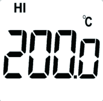
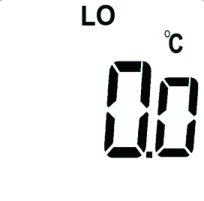
HI flashes when the result exceeds the set upper threshold. LO flashes below the lower threshold. If sound is enabled, the buzzer signals when a threshold is exceeded. When the result is between the thresholds, HI and LO are not displayed.
Settings
- 01In HOLD mode, hold the MODE button for more than 2 s. The upper HI threshold setting will open.
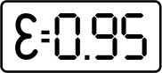
- 02Briefly press the MODE button repeatedly to cycle through: HI → LO → ε → temperature unit → audible alarm. Increase values with the LASER button (▲) and decrease them with the LOCK button (▼).
- 03To return to HOLD mode, press the trigger or wait 10 s without pressing any buttons.
| Setting | How to access | Adjustment: LASER (▲) / LOCK (▼) |
|---|---|---|
| Upper HI threshold | First screen | Brief press: change by 1; hold: change by 10 per second. |
| Lower LO threshold | 1 brief press of MODE | Brief press: change by 1; hold: change by 10 per second. |
| Emissivity ε | 2 brief presses of MODE | Brief press: change by 0.01; hold: change by 0.1 per second. |
| Temperature unit | 3 brief presses of MODE | Switch between °C / °F. |
| Audible alarm | 4 brief presses of MODE | Switch sound on / off. |
Ending measurement
- ■For manual measurement, release the trigger. SCAN will disappear, HOLD will appear and the last result will remain on the display.
- ■For locked measurement, press the trigger or briefly press the LOCK button. The padlock and SCAN will disappear, HOLD will appear and the last result will be retained.
Emissivity
Emissivity ε describes the ability of a material's surface to emit thermal energy. For most organic materials and painted or oxidised surfaces, it is approximately 0.95.
When measuring metal, cover the surface with masking tape or matt paint, set a high emissivity and wait until the tape or paint reaches the temperature of the underlying surface. The temperature of the covered surface then corresponds to the temperature of the metal.
Metals
| Surface | Emissivity ε |
|---|---|
| Aluminium - oxidised | 0.2–0.4 |
| A3003 alloy - oxidised | 0.3 |
| A3003 alloy - raw | 0.1–0.3 |
| Brass - polished | 0.3 |
| Brass - oxidised | 0.5 |
| Copper - oxidised | 0.4–0.8 |
| Copper - terminal strip | 0.6 |
| Hastelloy - alloy | 0.3–0.8 |
| Inconel - oxidised | 0.7–0.95 |
| Inconel - abrasive blasted | 0.3–0.6 |
| Inconel - electropolished | 0.15 |
| Iron - oxidised | 0.5–0.9 |
| Iron - rusted | 0.5–0.7 |
| Cast iron - oxidised | 0.6–0.95 |
| Cast iron - unoxidised | 0.2 |
| Cast iron - casting | 0.2–0.3 |
| Wrought iron - passivated | 0.9 |
| Lead - raw | 0.4 |
| Lead - oxidised | 0.2–0.6 |
| Molybdenum - oxidised | 0.2–0.6 |
| Nickel - oxidised | 0.2–0.5 |
| Platinum - black | 0.9 |
| Steel - cold-rolled | 0.7–0.9 |
| Steel - burnished | 0.4–0.6 |
| Steel - polished | 0.1 |
| Zinc - oxidised | 0.1 |
Non-metals
| Surface | Emissivity ε |
|---|---|
| Asbestos | 0.95 |
| Asphalt | 0.95 |
| Basalt | 0.7 |
| Carbon - unoxidised | 0.8–0.9 |
| Carbon - graphite | 0.7–0.8 |
| Silicon carbide (carborundum) | 0.9 |
| Ceramic | 0.95 |
| Clay | 0.95 |
| Concrete | 0.95 |
| Fabric | 0.9 |
| Convex glass | 0.76–0.8 |
| Smooth glass | 0.92–0.94 |
| Nonex glass | 0.78–0.82 |
| Sheet material | 0.96 |
| Gypsum | 0.8–0.95 |
| Ice | 0.98 |
| Limestone | 0.98 |
| Paper | 0.95 |
| Plastic | 0.95 |
| Water | 0.93 |
| Soil | 0.9–0.98 |
| Wood | 0.9–0.95 |
Maintenance
Have repairs carried out by the service centre - submit a request at wipcool.pl/serwis. The service centre should use original spare parts.
Cleaning
- 01Blow away loose debris with clean compressed air, then carefully wipe the lens surface with a damp cotton swab.
- 02Clean the housing periodically with a damp sponge or soft cloth.
Replacing the batteries
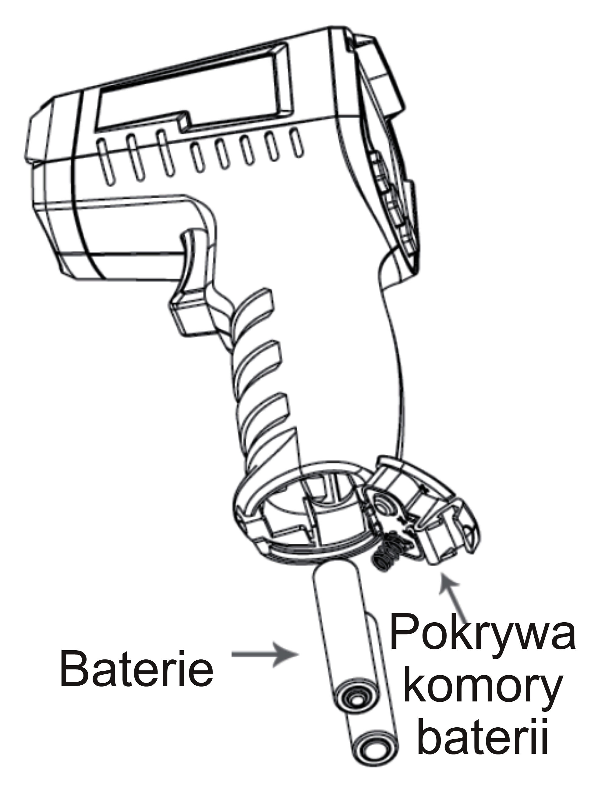
The infrared thermometer is powered by two AAA 1.5 V batteries of the same type. Do not charge the batteries.
- 01Turn the infrared thermometer over, slide the battery compartment cover in the direction of the arrow and lift it.
- 02If replacing the batteries, remove the used batteries. Insert the batteries according to the polarity markings.
- 03Close the battery compartment cover.
Troubleshooting
Display codes
| Code | Meaning | Solution |
|---|---|---|
| OL | The object temperature exceeds 500 °C. | Stop the measurement. |
| -OL | The object temperature is below -50 °C. | Stop the measurement. |
| Err | Ambient temperature outside the operating range. | Leave the infrared thermometer at 0–50 °C for 30 min. |
Other problems
| Problem | Possible cause | Solution |
|---|---|---|
| Battery symbol flashes | Low battery | Replace the batteries. |
| Laser does not work or is dim | Low battery | Replace the batteries. |
| Inaccurate measurement | Incorrect emissivity setting | Set the emissivity according to the ‘EMISSIVITY’ section. |
| Inaccurate measurement | Measurement distance too great | Select the distance according to D:S and the field of view. |
| Inaccurate measurement | Target diameter below 20 mm | Check the target size and field of view according to the ‘HOW TO USE’ section. |
Waste electrical and electronic equipment
- 01The crossed-out bin symbol means that the device must not be disposed of with other waste at the end of its life.
Under the applicable regulations on waste electrical and electronic equipment, products marked with the separate collection symbol must not be disposed of with other municipal waste. Because they contain hazardous substances, electronic products that are not collected separately may pose a risk to the environment and human health. Proper separate collection of waste electrical and electronic equipment prevents adverse effects on the environment.
By taking waste equipment to a collection point, the user contributes to its reuse, recycling and recovery.
Recycling - one method of protecting the environment. The process of recovering substances from waste that can be reused as raw materials.
Waste recovery - the use of waste that has lost its utility value, such as plastics, paper and cardboard, as secondary raw materials (also commonly used to mean destruction).
Information on the collection system for waste electrical and electronic equipment
- ■Waste electrical and electronic equipment must not be disposed of with other waste.
- ■The collection of incomplete electrical and electronic equipment and parts from waste equipment is prohibited.
- ■A distributor delivering equipment intended for households to a purchaser must collect waste household equipment free of charge at the place of delivery, provided that the waste equipment is of the same type and performs the same function as the equipment delivered.
- ■The user may hand over waste equipment to a waste equipment collector, a treatment facility or a municipal waste collector in the municipality.
- ■Information on collection points is available on the BIP websites of regional, city and municipal authorities.
Service and documents
Before submitting a request, prepare:
- ■Model - shown on the device's nameplate and on the invoice.
- ■Serial number - if there is none, provide the production number (e.g. 11/2025), usually found on the underside of the device.
- ■Proof of purchase - an invoice or receipt from an authorised distributor.
- ■Description of the fault - what is happening, when it started and under what conditions.
Submit a service request at wipcool.pl/serwis. You will also find the warranty terms there.
Warranty period: 1 year.