
 Distribution PL · 4REF
Wipcool ALD-1 user manual
Read the entire manual before first use. Keep it for as long as you use the device.
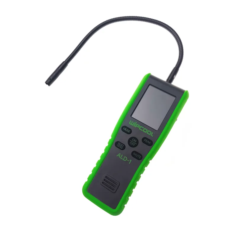
Wipcool ALD-1 user manual
The Wipcool ALD-1 is an infrared refrigerant leak detector. It is used to detect refrigerant leaks in air conditioning and refrigeration systems.
The user manual is an integral part of the product. Please read this manual carefully and follow all instructions strictly.
General information
Wipcool products are designed for professional use by qualified air conditioning and refrigeration engineers. As the manufacturer, Wipcool specifies that our equipment should only be operated by suitably qualified and trained personnel.
- ■Observe all local safety regulations and general safety standards when using the Wipcool ALD-1 infrared refrigerant leak detector.
- ■The user manual should be kept near the device so that personnel can access it easily at all times.
- ■Before use, qualified personnel should read the user manual carefully and understand all the instructions it contains.
- ■The manufacturer accepts no liability for any damage resulting from improper use, failure to follow the user manual, lack of personnel qualifications or any unauthorised modifications to the device.
- ■The general terms and conditions of sale contained in the sales documents apply.
Symbols and conventions
Symbols and markings used on the device and in the manual:
- 01
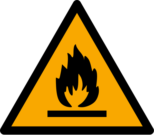 Warning of flammable substances.
- 02
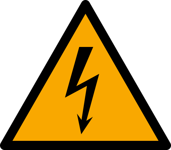 Dangerous voltage - risk of electric shock.
- 03
 Warning - read the text in the box next to the symbol.
- 04
 Wear eye protection.
- 05
 Notice - risk of damage to the device or an incorrect result.
- 06
 A tip to make the task easier.
- 07
 Indicates that the product meets the health, safety and environmental standards applicable in the European Union.
- 08RoHSThe product meets the requirements for restricting the use of hazardous substances.
- 09
 Do not dispose of the device with household waste.
Safety information
- ■Check the detector and accessories before use. If the housing is damaged, the display does not work or you suspect a malfunction, stop work.
- ■Do not open the detector or alter its internal wiring.
- ■Do not use or store the detector in places with high temperatures, high humidity or strong electromagnetic fields.
Technical specifications
Device diagram
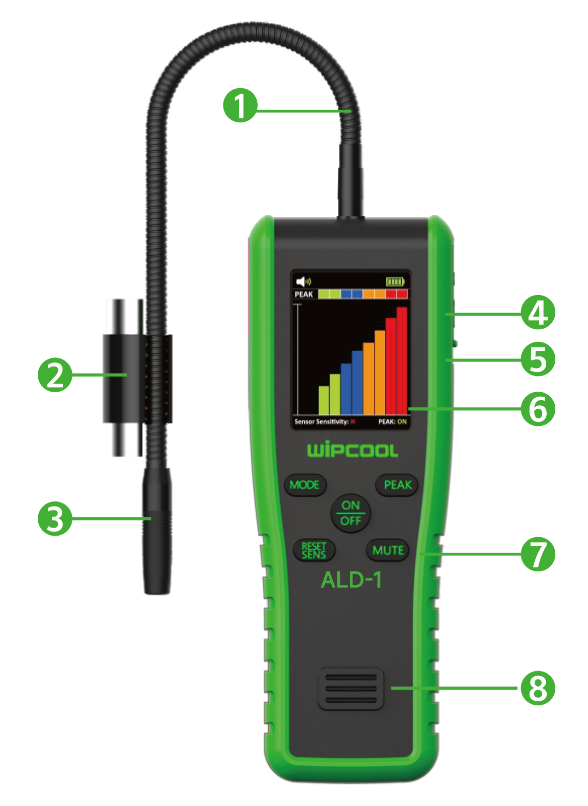
| No. | Component |
|---|---|
| 1 | Flexible probe |
| 2 | UV lamp |
| 3 | Filter |
| 4 | Headphone socket |
| 5 | USB-C port |
| 6 | Display |
| 7 | Buttons |
| 8 | Buzzer |
Buttons
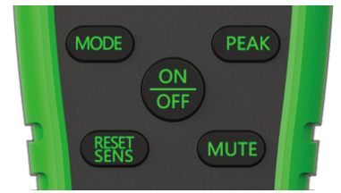
| Button | Function |
|---|---|
| ON/OFF | Press and hold for 2 s to turn on the detector; press again to turn it off. |
| RESET SENS | Selects the sensitivity level: low, medium or high. |
| MUTE | Turns the buzzer on or off. |
| PEAK | Turns the peak value function on or off. |
| MODE | Reserved button. |
Display
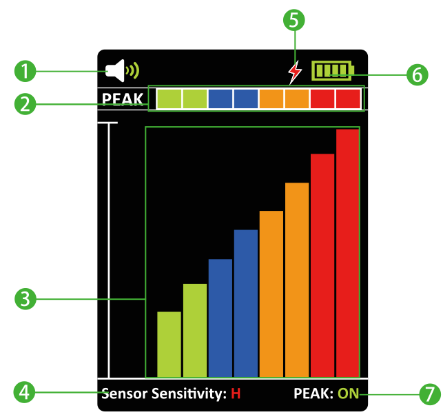
| No. | Indication |
|---|---|
| 1 | Buzzer: red icon - off; green - on. |
| 2 | Peak value: the highest recorded reading, displayed when the PEAK function is on. |
| 3 | Current reading: the higher the relative refrigerant concentration, the higher the bars. |
| 4 | Sensitivity: H - high, M - medium, L - low. |
| 5 | Charging indicator. |
| 6 | Battery charge level: green - full; yellow - low; red - very low, charge the battery as soon as possible. |
| 7 | PEAK ON/OFF: peak value function on / off. Turning it off clears the recorded peak value. |
Package contents
After unpacking, check that the set is complete and in good condition. Report any missing or damaged items to the seller.
| Item | Quantity |
|---|---|
| ALD-1 detector | 1 pc. |
| User manual | 1 pc. |
| UV lamp | 1 pc. |
| Case | 1 pc. |
| USB-C charging cable | 1 pc. |
| Replacement filters | 5 pcs. |
A power adapter for charging is not included.
Transport and storage
- ■Transport the detector in its original packaging.
- ■Store the detector in a dry place, away from direct sunlight and heat sources, at a temperature of -20–+60 °C.
- ■Charge the battery before prolonged storage. Do not store the detector for more than 6 months without charging it.
How to use
Charging the battery
- 01Connect the charging cable to the detector's USB-C port and a 5 V DC / 1 A power adapter.
- 02Fully charge the battery. The charging indicator lights up orange during charging and green when charging is complete.
Detection conditions
Move the probe during detection. The ALD-1 detects changes in relative gas concentration; if the probe is stationary and the concentration remains unchanged, it will not indicate the exact location of the leak.
- ■Before testing, check that the system pressure is at least 3.4 bar. Many leaks cannot be detected at low pressure.
- ■Do not place the detector close to organic solvents, detergents or high-voltage equipment.
- ■Check that the battery has enough charge for the entire test, which usually takes approximately 30 min.
Detecting a leak
1. Turn on the detector using the ON/OFF button and wait for the warm-up countdown to finish. The main screen will appear after approximately 30 s.
2. Select the sensitivity using the RESET SENS button. The default setting is high.
3. Inspect the tubes, hoses, fittings and service valves throughout the system. Look for signs of oil, damage and corrosion. Check in particular:
- ■tube connections;
- ■points where the tube cross-section changes;
- ■points where the vertical direction of the tube changes.
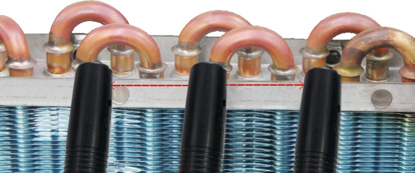
4. Move the probe back and forth over suspected areas at approximately 75 mm/s. Keep the tip no more than 6 mm from the area being tested.
5. Watch the bars on the screen and listen to the buzzer if it is on. Rising bars and faster signals indicate an increase in the detected concentration.
6. Check the entire system in this way and mark each detected leak location.
Automatic shut-off
The detector turns off automatically after 10 min of inactivity.
Finishing the measurement
After use, turn off the detector using the ON/OFF button.
Maintenance
General recommendations
Have repairs carried out by the service department - submit a request at wipcool.pl/serwis.
Clean the housing with a soft, damp cloth and a mild detergent. Do not use abrasive cleaners or solvents.
Battery
Replacing the filter
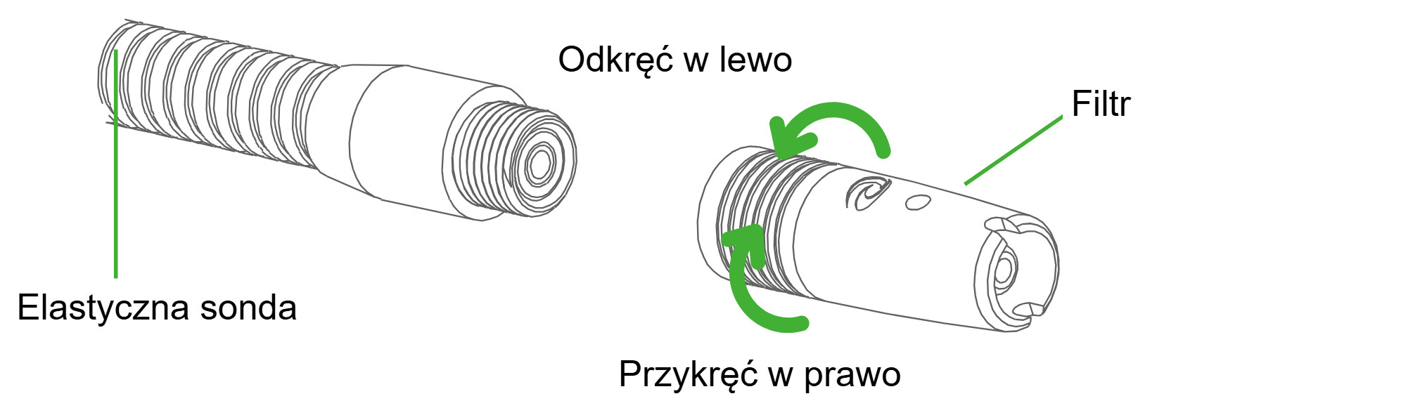
The filter traps large contaminants and moisture, reducing false alarms. Replace it when it is heavily soiled (black and clogged).
- 01Unscrew the filter by turning it anticlockwise.
- 02Screw on the new filter by turning it clockwise.
Waste electrical and electronic equipment
- 01The crossed-out bin symbol means that the device must not be disposed of with other waste at the end of its life.
Under applicable regulations on waste electrical and electronic equipment, products marked with the separate collection symbol must not be placed with other municipal waste. Because they contain harmful substances, electronic products that are not separately sorted may be hazardous to the environment and human health. Proper separate collection of waste electrical and electronic equipment prevents adverse effects on the environment.
By taking waste equipment to a collection point, the user contributes to its reuse, recycling and recovery.
Recycling - one method of protecting the environment. The process of recovering substances from waste that can be reused as raw materials.
Waste recovery - the use of waste that has lost its practical value, such as plastics, paper and cardboard, as secondary raw materials; the term is also commonly used to mean its destruction.
Information on the collection system for waste electrical and electronic equipment
- ■Waste electrical and electronic equipment must not be placed with other waste.
- ■The collection of incomplete electrical and electronic equipment and parts from waste equipment is prohibited.
- ■A distributor delivering equipment intended for households to a purchaser must collect household waste equipment free of charge at the place of delivery, provided that the waste equipment is of the same type and performs the same function as the equipment delivered.
- ■The user may hand over waste equipment to a waste equipment collector, a treatment facility or a municipal waste collector in the municipality.
- ■Information about collection points is available on the BIP websites of regional, city and municipal authorities.
Batteries and rechargeable batteries
- 01The crossed-out bin symbol on a battery or rechargeable battery means that it must be collected separately from other waste at the end of its life. It must not be disposed of with municipal waste.
- ■Take used batteries and rechargeable batteries to a collection point. If possible, remove them from the device before taking it for collection.
- ■Substances contained in batteries can harm the environment and health, particularly if a battery is damaged or leaking. Separate collection allows them to be processed safely and raw materials to be recovered.
- ■The Cd or Pb marking below the bin symbol means that the battery contains more than 0.002% cadmium or more than 0.004% lead.
The ALD-1 detector's battery is built in - do not remove it yourself. Take the detector to a collection point with the battery installed.
Service and documents
Before submitting a service request, prepare:
- ■Model - shown on the device's nameplate and on the invoice.
- ■Serial number - if there is none, provide the production number (e.g. 11/2025), usually found on the underside of the device.
- ■Proof of purchase - an invoice or receipt from an authorised distributor.
- ■Description of the fault - what is happening, since when and under what conditions.
You can submit a service request at wipcool.pl/serwis. You will also find the warranty terms there.