
 Distribution PL · 4REF
Wipcool ALD-2 user manual
Read the entire manual before first use. Keep it for as long as you use the device.
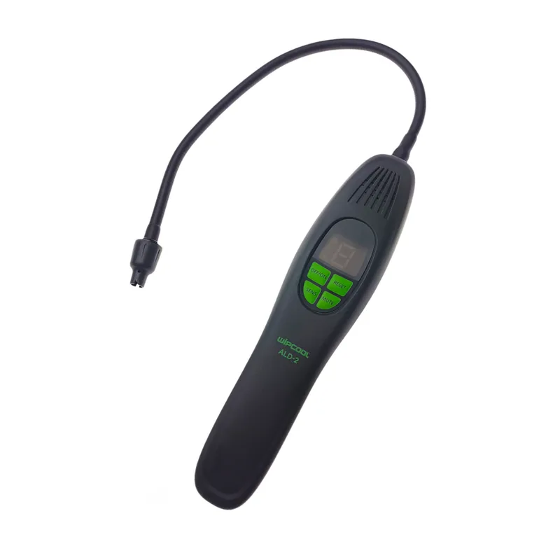
Wipcool ALD-2 user manual
The handheld Wipcool ALD-2 refrigerant leak detector has a heated diode sensor and is used to detect refrigerant leaks. The flexible probe provides access to hard-to-reach areas.
The user manual is an integral part of the product. Read this manual carefully and follow all instructions strictly.
General information
Wipcool products are designed for professional use by qualified air conditioning and refrigeration engineers. As the manufacturer, Wipcool stipulates that its equipment should only be operated by people with appropriate qualifications and training.
- ■Follow all local safety regulations and general safety standards when using the Wipcool ALD-2 refrigerant leak detector.
- ■The user manual should be kept near the device so that personnel can easily access it at all times.
- ■Before use, qualified personnel should read the user manual carefully and understand all the instructions it contains.
- ■The manufacturer accepts no liability for any damage resulting from improper use, failure to follow the user manual, lack of personnel qualifications or any unauthorised modifications to the device.
- ■The general terms of sale contained in the sales documents apply.
Symbols and conventions
Symbols and markings used on the device and in the manual:
- 01
 Dangerous voltage - risk of electric shock.
- 02
 Warning - read the text in the box next to the symbol.
- 03
 Notice - risk of damage to the device or an incorrect result.
- 04
 Indicates that the product meets the health, safety and environmental standards applicable in the European Union.
- 05RoHSThe product meets the requirements for restricting the use of hazardous substances.
- 06
 Do not dispose of the detector with household waste.
Safety information
- ■Do not dismantle the detector housing. Only unscrew the probe housing when replacing the sensor.
Technical specifications
Device diagram
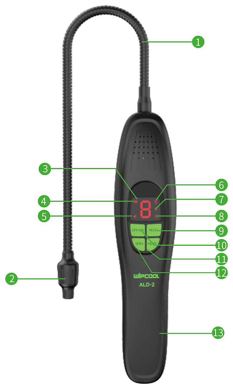
| No. | Name |
|---|---|
| 1 | Flexible probe |
| 2 | Sensor |
| 3 | Display |
| 4 | Three-colour battery level indicator |
| 5 | Buzzer icon |
| 6 | Alarm icon |
| 7 | Automatic zeroing icon |
| 8 | Three-colour sensitivity indicator |
| 9 | Zeroing button (RESET) |
| 10 | Power button (ON/OFF) |
| 11 | Mute button (MUTE) |
| 12 | Sensitivity adjustment button (SENS) |
| 13 | Battery compartment |
Buttons
| Button | Function |
|---|---|
| ON/OFF | Switches the detector on and off. |
| RESET | Zeros the reading and selects the zeroing mode; see ‘Automatic and manual zeroing’. |
| MUTE | Switches the sound on and off; see ‘Leak alarm and mute’. |
| SENS | Selects the sensitivity level; see ‘Sensitivity adjustment’. |
Package contents
After unpacking, check that the package is complete and in good condition. Report any missing or damaged items to the seller.
| Item | Quantity |
|---|---|
| ALD-2 refrigerant leak detector | 1 pc. |
| Heated diode sensor | 1 pc. |
| User manual | 1 pc. |
Batteries are sold separately.
Transport and storage
- ■Transport the device in its original packaging to prevent damage.
- ■Store the detector and sensor in a dry, clean place, away from direct sunlight and heat sources, at a temperature of -20 to +60 °C.
- ■Remove the batteries if the device will not be used for an extended period.
Application
The ALD-2 detects refrigerants from the groups listed in the table, as well as nitrogen and hydrogen mixtures (N₂/H₂) used as forming gas for leak testing.
| Group | Refrigerant examples |
|---|---|
| CFC | R12, R11, R500, R503 |
| HCFC | R22, R123, R124, R502 |
| HFC | R134a, R404A, R410A, R407C, R32 |
| HC | R600a, R290 |
| HFO | R1234yf |
How to use
Before first use, insert the batteries as described in ‘Replacing the batteries’ (section ‘MAINTENANCE’).
Start-up
- 01Press the power button. The detector will begin warming up, during which the middle segment of the display flashes. Wait 30 s.
- 02Check that ‘0’ is flashing on the display, the buzzer icon is lit and one beep per second is audible. This indicates that the detector is ready for use.
- 03After warm-up, the automatic zeroing icon is lit and the sensitivity indicator is red. If necessary, change the zeroing mode or sensitivity level, or mute the sound.
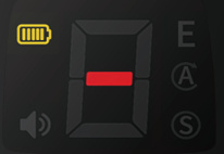
Battery level indicator
| Indicator colour | Battery level |
|---|---|
| Green | High |
| Orange | Medium |
| Flashing red | Low |
Sensitivity adjustment
Press the sensitivity adjustment button (SENS) repeatedly to select one of three levels:
| Indicator colour | Sensitivity |
|---|---|
| Red | High |
| Orange | Medium |
| Green | Low |
Leak alarm and mute
The detector signals a leak visually and audibly. The display shows an alarm level from 1 to 7. The higher the refrigerant concentration, the higher the reading and the more frequent the beeps. The audible alarm is enabled after warm-up. Press the mute button to switch the sound off or back on; the visual indication remains active.
Automatic and manual zeroing
Zeroing sets the reading relative to the background concentration around the probe. In automatic zeroing mode, which is enabled by default, the detector compensates for the background and gives an alarm when a higher concentration is detected.
To enter manual zeroing mode, hold down the zeroing button (RESET) until the automatic zeroing icon goes out. In manual zeroing mode, briefly press the zeroing button to set the reference level. ‘8’ will appear on the display for 3 s, indicating that zeroing is complete. From this point, the detector indicates concentrations higher than the established background. To return to automatic zeroing mode, hold down the zeroing button until the automatic zeroing icon lights up.
Zeroing at a low background concentration increases sensitivity, while zeroing at a high concentration reduces it.
Automatic shut-off
The detector switches off automatically after 30 min of inactivity (no buttons pressed). Each button press restarts the countdown.
Detection conditions
- ■Carry out the test in nearly still air. Wind dilutes or carries refrigerant away from the leak site and reduces test accuracy.
- ■If refrigerant from a known leak is present in the air, ventilate the area with a fan. Carry out the test itself without airflow.
- ■Check oily or dusty areas, valves and tube connections first.
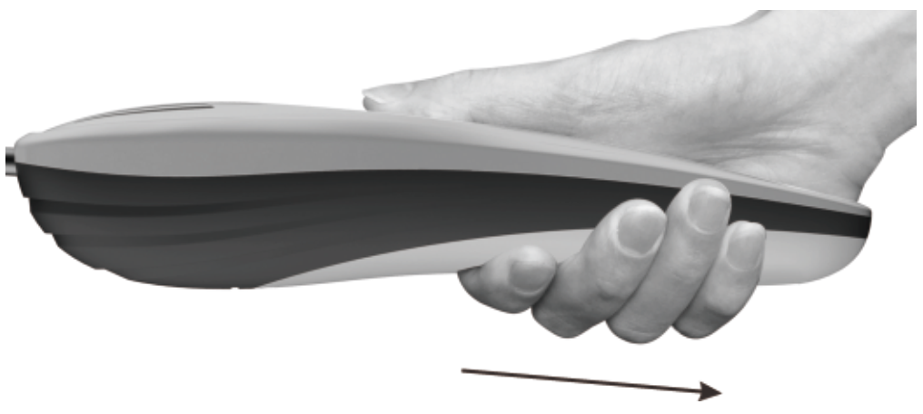
- ■Hold the probe 3–5 mm from the test point to prevent it from becoming contaminated with oil or other substances. Move it at approximately 25–50 mm/s.
Locating a leak
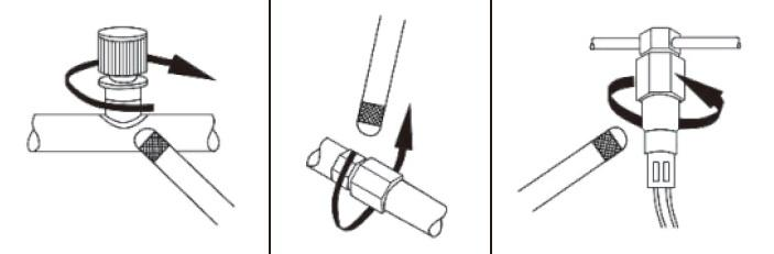
- 01Bend the flexible probe to the required shape and slowly move it into the area where you suspect a leak. Use high sensitivity to initially locate the leak area.
- 02When an alarm occurs, check the surrounding area again and make sure the signal repeats.
- 03Move the probe from an area with no alarm towards the suspected point. Select a lower sensitivity and repeat the test, zeroing the reading if necessary, to pinpoint the leak more accurately.
- 04Mark the identified point. Before the next test, move the detector away from the detected leak for 10 s, then check the remaining points in the system.
Finishing the measurement
When finished, hold down the power button (ON/OFF) until the detector switches off.
Maintenance
Replacing the batteries
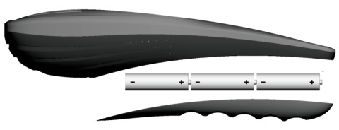
Power supply: three AA 1.5 V alkaline batteries.
- 01Switch off the detector and open the battery compartment cover. Remove the used batteries if present.
- 02Insert new batteries according to the polarity markings.
- 03Close the battery compartment cover.
Cleaning
Switch off the detector before cleaning. Wipe the sensor with a soft cotton cloth or clean it with a stream of dry gas. Remove water droplets, oil, grease, dust and other contaminants from its surface.
Replacing the sensor
Under normal conditions, the sensor can operate for at least one year. Frequent operation at high refrigerant concentrations significantly reduces its service life. Replace a worn sensor.
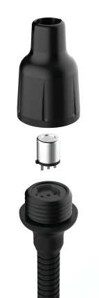
- 01Switch off the detector and unscrew the probe housing.
- 02Replace the sensor and check that it makes proper contact with the socket.
- 03Screw the probe housing back on.
Troubleshooting
| Code | Meaning |
|---|---|
| 1E | Probe power supply failure |
| 2E | Probe missing or damaged |
| 3E | Fan stopped |
| Problem | Possible cause | Solution |
|---|---|---|
| Code 2E | Probe missing or damaged | Check that the sensor is seated correctly in the probe tip (see ‘Replacing the sensor’). Then restart the detector and wait until it has finished warming up. |
| Probe does not heat up | Probe heating fault | Have the device repaired by the service centre - submit a request at wipcool.pl/serwis. |
Waste electrical and electronic equipment
- 01The crossed-out bin symbol means that the used device must not be disposed of with other waste.
Under the applicable regulations on waste electrical and electronic equipment, products marked with the separate collection symbol must not be disposed of with other municipal waste. Because they contain hazardous substances, electronic products that are not collected separately may pose a risk to the environment and human health. Proper separate collection of waste electrical and electronic equipment prevents negative effects on the environment.
By taking used equipment to a collection point, the user contributes to its reuse, recycling and recovery.
Recycling - one method of protecting the environment. The process of recovering substances from waste that can be reused as raw materials.
Recovery - the use (also commonly understood as destruction) of waste that has lost its useful value, such as plastics, paper and cardboard, as secondary raw materials.
Information on the waste electrical and electronic equipment collection system
- ■Waste electrical and electronic equipment must not be disposed of with other waste.
- ■The collection of incomplete electrical and electronic equipment and parts from waste equipment is prohibited.
- ■A distributor delivering equipment intended for households to a purchaser must collect waste household equipment free of charge at the place of delivery, provided that the waste equipment is of the same type and performs the same function as the equipment delivered.
- ■The user may hand over waste equipment to a waste equipment collector, a treatment facility or a municipal waste collector in the municipality.
- ■Information on collection points is available on the Public Information Bulletin (BIP) websites of regional marshal's offices and city and municipal offices.
Batteries and rechargeable batteries
- 01The crossed-out bin symbol on a battery or rechargeable battery means that it must be collected separately from other waste when spent. It must not be disposed of with municipal waste.
- ■Take spent batteries and rechargeable batteries to a collection point. If possible, remove them from the device before taking it for collection.
- ■Substances contained in batteries can harm the environment and health, particularly if a battery is damaged or leaking. Separate collection allows them to be processed safely and raw materials to be recovered.
- ■The Cd or Pb marking beneath the bin symbol means that the battery contains more than 0.002% cadmium or more than 0.004% lead.
Service and documents
Before submitting a request, prepare:
- ■Model - shown on the device nameplate and invoice.
- ■Serial number - if absent, provide the production number (e.g. 11/2025), usually found on the underside of the device.
- ■Proof of purchase - an invoice or receipt from an authorised distributor.
- ■Description of the fault - what is happening, when it started and under what conditions.
You can submit a service request at wipcool.pl/serwis. You will also find the warranty terms there.