
 Distribution PL · 4REF
Wipcool APC1000 user manual
Read the entire manual before first use. Keep it for as long as you use the device.
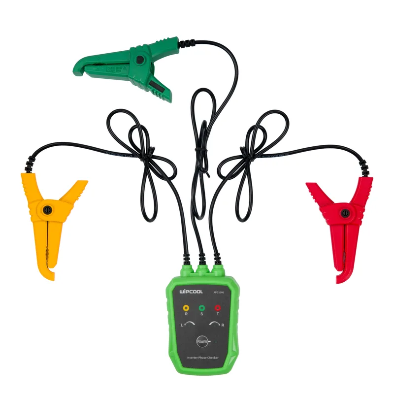
Wipcool APC1000 user manual
The Wipcool APC1000 non-contact phase rotation tester is used to check phase rotation and the presence of voltage, and to locate breaks in conductors. The clamps are attached to the insulation of the conductors without disconnecting them or exposing the cores.
The user manual is an integral part of the product. Please read this manual carefully and follow all instructions strictly.
General information
Wipcool products are designed for professional use by qualified air conditioning and refrigeration engineers. As the manufacturer, Wipcool stipulates that our equipment should only be operated by people with the appropriate qualifications and training.
- ■Observe all local safety regulations and general safety standards when using the Wipcool APC1000 non-contact phase rotation tester.
- ■The user manual should be kept near the instrument so that personnel can access it easily at any time.
- ■Before use, qualified personnel should read the user manual carefully and understand all the instructions it contains.
- ■The manufacturer accepts no liability for any damage resulting from improper use, failure to follow the user manual, lack of personnel qualifications or any unauthorised modifications to the instrument.
- ■The general terms of sale contained in the sales documents apply.
Symbols and conventions
Symbols and markings used on the instrument and in the manual:
- 01
 Hazardous voltage - risk of electric shock.
- 02
 Warning of fire or explosion hazard near flammable gases and liquids.
- 03
 Notice - risk of damage to the instrument or an incorrect result.
- 04~ / ACAlternating current.
- 05CAT IIIMeasurement category for distribution circuits in low-voltage installations in buildings.
- 06CAT IVMeasurement category for circuits at the source of low-voltage installations in buildings.
- 07
 Indicates that the product meets the health, safety and environmental standards applicable in the European Union.
- 08
 Do not dispose of the instrument with household waste.
Safety information
- ■Before use, read the labels and symbols on the front and back of the instrument.
- ■Before each use, check the condition of the instrument, connecting leads, clamps and batteries. Do not use damaged equipment or equipment with exposed or broken leads.
- ■Only authorised persons with appropriate qualifications may carry out disassembly, repairs and maintenance.
- ■Do not modify the instrument or use non-original accessories.
- ■Use the instrument in accordance with the manual. Other use may reduce or invalidate the protection provided.
- ■If using the instrument creates a hazard, stop work and secure it against further use. Have its condition assessed by a person authorised to carry out repairs.
Technical specifications
Instrument diagram
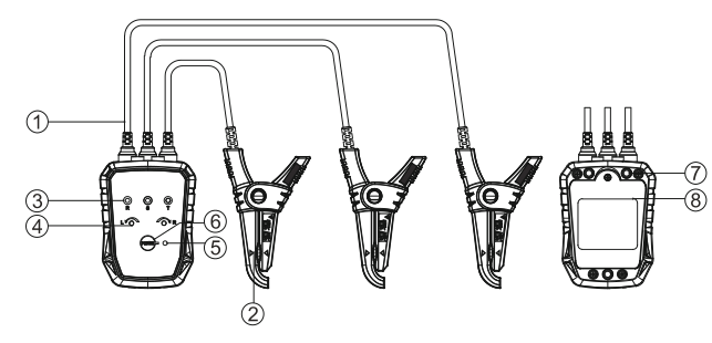
| No. | Name |
|---|---|
| 1 | Connecting leads |
| 2 | Clamps |
| 3 | R, S, T phase indicator lights |
| 4 | R and L phase rotation indicator lights |
| 5 | POWER indicator light |
| 6 | POWER button |
| 7 | Magnet |
| 8 | Battery compartment |
Buttons
| Button | Function |
|---|---|
| POWER | Switches the instrument on and off. |
Package contents
After unpacking, check that the package is complete and in good condition. Report any missing or damaged items to the seller.
| Item | Quantity |
|---|---|
| APC1000 instrument | 1 pc. |
| Bag | 1 pc. |
| AA 1.5 V battery | 2 pcs. |
| User manual | 1 pc. |
| Certificate | 1 pc. |
Transport and storage
- ■Transport the instrument in its original packaging.
- ■Store the instrument in a dry place, away from direct sunlight and heat sources, at a temperature of -20 to +60 °C. Storage humidity: below 90% RH, non-condensing.
- ■Remove the batteries if the instrument will not be used for an extended period.
How to use
Before first use, insert the batteries as described in ‘Replacing the batteries’ (MAINTENANCE section).
Phase designations
| First phase | Second phase | Third phase |
|---|---|---|
| A | B | C |
| L1 | L2 | L3 |
| R | S | T |
| U | V | W |
Checking phase rotation
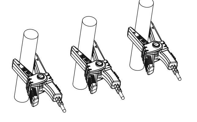
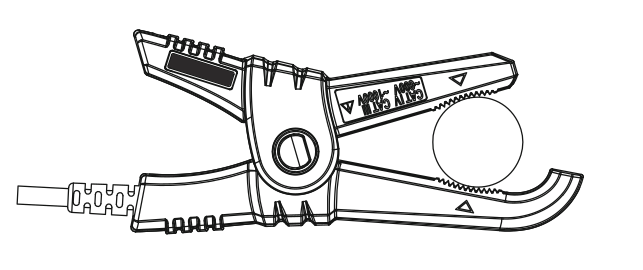
- 01Attach the three clamps to three separate phase conductors, positioning each conductor between the ▲ and ▼ markers on the clamp. The initial order of the clamps can be arbitrary.
- 02Press POWER. The blue POWER indicator light should illuminate and the buzzer should sound once. If the light does not illuminate, check the causes in the ‘TROUBLESHOOTING’ section.
- 03Read the phase rotation according to the table below.
| Phase rotation | Phase indicator lights | Phase rotation indicator light | Sound |
|---|---|---|---|
| Clockwise | R, S, T illuminated | R illuminated green | Slow intermittent |
| Anticlockwise | R, S, T illuminated | L illuminated red | Fast intermittent |
Testing a single conductor
- 01Switch on the instrument using the POWER button.
- 02Attach any clamp to the insulation of the conductor under test so that the conductor is between the ▲ and ▼ markers. At a voltage of 70–1000 V AC, the R, S and T lights will illuminate.
Locating a break
- 01Switch on the instrument using the POWER button and attach one clamp to the insulation of the conductor under test.
- 02When the R, S and T lights are illuminated, start moving the clamp along the conductor. If the R, S and T lights suddenly go out, the break is in the section the clamp has already passed.
Automatic switch-off
The instrument switches off automatically after 5 min of inactivity.
Finishing a measurement
After measurement, check the POWER indicator light. If it is illuminated, press POWER to switch off the instrument. The light will go out and the buzzer will sound once. Then remove the clamps from the conductors.
Maintenance
Repairs
Have repairs carried out by the service centre - submit a request at wipcool.pl/serwis.
Cleaning
- ■Clean the housing with a soft, damp cloth. Do not use corrosive agents or solvents. Do not use alcohol.
Replacing the batteries
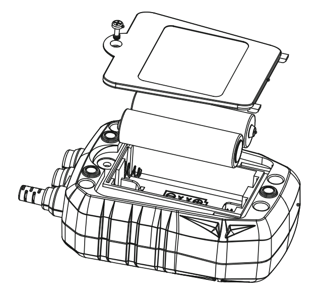
- 01Switch off the instrument and remove the clamps from the conductors as described in ‘Finishing a measurement’ (HOW TO USE section).
- 02Loosen the screw and remove the battery compartment cover.
- 03Remove both batteries. Insert new AA 1.5 V alkaline batteries according to the polarity markings.
- 04Fit the battery compartment cover and tighten the screw.
- 05Press POWER and check that the instrument switches on. If it does not switch on, check the batteries or repeat the replacement from step 1.
Troubleshooting
Service repairs include replacement of the battery contacts and connecting lead, and repair or replacement of the printed circuit board.
| Problem | Possible cause | Solution |
|---|---|---|
| Instrument cannot be switched on; POWER indicator light is off | Batteries missing | Insert the batteries. |
| Instrument cannot be switched on; POWER indicator light is off | Incorrect battery type | Replace the batteries with the correct type. |
| Instrument cannot be switched on; POWER indicator light is off | Batteries discharged | Replace the batteries. |
| Instrument cannot be switched on; POWER indicator light is off | Incorrect polarity | Insert the batteries according to the polarity markings. |
| Instrument cannot be switched on; POWER indicator light is off | Poor battery contact | Have repairs carried out by the service centre - submit a request at wipcool.pl/serwis. |
| Instrument cannot be switched on; POWER indicator light is off | Battery compartment cover not fully closed | Fit the battery compartment cover and tighten the screw. |
| Instrument cannot be switched on; POWER indicator light is off | Damaged circuit component | Have repairs carried out by the service centre - submit a request at wipcool.pl/serwis. |
| Indicator lights are dim | Batteries discharged | Replace the batteries. |
| Measurement cannot be performed | No voltage in the three-phase conductors | This is not an instrument fault. |
| Measurement cannot be performed | Clamp cannot grip a thin conductor | Wrap the thin conductor around the clamp. |
| Measurement cannot be performed | Clamp fitted incorrectly | Refit the clamp as shown in figure 3. |
| Measurement cannot be performed | Broken connecting lead | Have repairs carried out by the service centre - submit a request at wipcool.pl/serwis. |
| Measurement cannot be performed | Damaged circuit component | Have repairs carried out by the service centre - submit a request at wipcool.pl/serwis. |
Waste electrical and electronic equipment
- 01The crossed-out bin symbol means that the discarded instrument must not be disposed of with other waste.
Under applicable regulations on waste electrical and electronic equipment, products marked with the separate collection symbol must not be disposed of with other municipal waste. Because they contain hazardous substances, electronic products that are not collected separately may be dangerous to the environment and human health. Proper separate collection of waste electrical and electronic equipment prevents adverse effects on the environment.
By taking waste equipment to a collection point, the user contributes to its reuse, recycling and recovery.
Recycling - one method of protecting the environment. The process of recovering substances from waste that can be reused as raw materials.
Recovery - the use of waste that has lost its useful value, such as plastics, paper and cardboard, as secondary raw materials; the term is also commonly used to mean destruction.
Information about the collection system for waste electrical and electronic equipment
- ■Waste electrical and electronic equipment must not be disposed of with other waste.
- ■The collection of incomplete electrical and electronic equipment and parts from waste equipment is prohibited.
- ■A distributor delivering equipment intended for households to a buyer must collect household waste equipment free of charge at the place of delivery, provided that the waste equipment is of the same type and performs the same function as the equipment delivered.
- ■The user may hand over waste equipment to a waste equipment collector, a treatment facility or a municipal waste collector in the municipality.
- ■Information about collection points is available on the public information bulletin (BIP) websites of regional, city and municipal authorities.
Batteries and rechargeable batteries
- 01The crossed-out bin symbol on a battery or rechargeable battery means that it must be collected separately from other waste when spent. It must not be disposed of with municipal waste.
- ■Take spent batteries and rechargeable batteries to a collection point. If possible, remove them from the instrument before handing it over for collection.
- ■Substances contained in batteries can harm the environment and health, particularly if a battery is damaged or leaking. Separate collection allows them to be processed safely and raw materials to be recovered.
- ■The Cd or Pb marking below the bin symbol means that the battery contains more than 0.002% cadmium or more than 0.004% lead.
Service and documents
Before submitting a request, prepare:
- ■Model - found on the instrument's rating plate and on the invoice.
- ■Serial number - if there is none, provide the production number (e.g. 11/2025), usually found on the underside of the instrument.
- ■Proof of purchase - an invoice or receipt from an authorised distributor.
- ■Description of the fault - what happens, when it started and under what conditions.
Submit a service request at wipcool.pl/serwis. You will also find the warranty terms there.
Warranty period: 1 year.