
 Distribution PL · 4REF
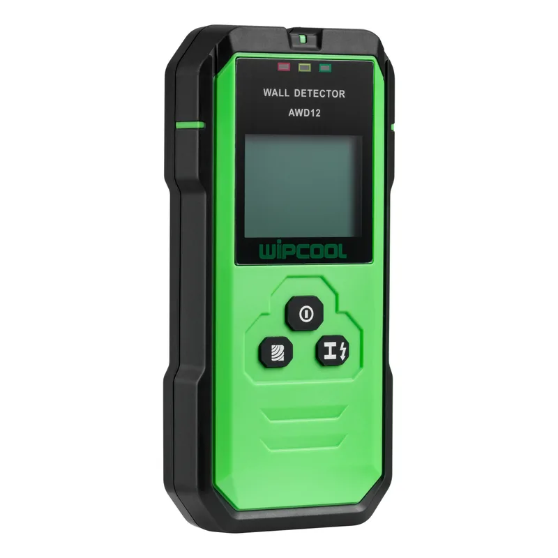
Wipcool AWD12 user manual
Read the entire manual before first use. Keep it for as long as you use the device.
Wipcool AWD12 user manual
The Wipcool AWD12 Cable Detector is used to detect metal and cables concealed in walls, ceilings and floors. It also detects wooden beams behind plasterboard.
The user manual is an integral part of the product. Please read this manual carefully and follow all instructions closely.
General information
Wipcool products are designed for professional use by qualified air conditioning and refrigeration technicians. As the manufacturer, Wipcool stipulates that our devices should be operated only by suitably qualified and trained persons.
- ■Observe all local safety regulations and general safety standards when using the Wipcool AWD12 Cable Detector.
- ■The user manual should be kept near the device so that personnel can access it easily at any time.
- ■Before use, qualified personnel should read the user manual carefully and understand all the instructions it contains.
- ■The manufacturer accepts no liability for any damage resulting from improper use, failure to follow the user manual, lack of qualified personnel or any unauthorised modifications to the device.
- ■The general terms and conditions of sale contained in the sales documents apply.
Symbols and conventions
Symbols and markings used on the device and in the manual:
- 01
 Dangerous voltage - risk of electric shock.
- 02
 Indicates that the product meets the health, safety and environmental standards applicable in the European Union.
- 03RoHSThe product meets the requirements for restricting the use of hazardous substances.
- 04
 Do not dispose of the device with household waste.
AC means alternating voltage.
Safety information
- ■Do not allow moisture to enter the detector and protect it from direct sunlight.
- ■After a significant change in temperature, wait until the detector reaches ambient temperature before switching it on.
- ■Devices that emit signals, such as microwave ovens, and strong magnetic or electromagnetic fields can interfere with detection.
- ■Moisture, metal building materials, aluminium insulation facings, and conductive wallpaper, floor coverings and tiles also affect the result. Take these conditions and information about the building into account before starting work.
Technical specifications
The result depends on the size and material of the object being detected and on the material and condition of the scanned surface. The detection depth is lower for a cable that is not live.
The maximum AC detection depth of 50 mm applies to a cable energised at 220 V / 50 Hz.
Device diagram
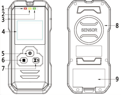
| No. | Name |
|---|---|
| 1 | Red indicator light |
| 2 | Yellow indicator light |
| 3 | Green indicator light |
| 4 | Display |
| 8 | Detection area (SENSOR) |
| 9 | Battery compartment |
Buttons
| No. | Name and function |
|---|---|
| 5 | ON/OFF button (switches the device on and off) |
| 6 | Wood mode button |
| 7 | Metal/AC mode button |
Sound
Press the wood mode button (6) and the metal/AC mode button (7) at the same time to turn the sound on or off.
Display
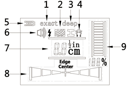
| No. | Meaning |
|---|---|
| 1 | Exact wood detection mode. |
| 2 | Current mode: detection of metal, live AC cables or wood. |
| 3 | Deep wood detection mode. |
| 4 | Magnetic and non-magnetic metal symbols. |
| 5 | Battery level indicator. |
| 6 | Sound icon. |
| 7 | Depth of detected metal - distance from the centre of the detection area to the object. cm stands for centimetres and in stands for inches. |
| 8 | Edge indicates the edge and Center indicates the centre of the detected object in wood mode. Only Center appears in metal and AC modes. |
| 9 | Detection signal strength - scale and percentage value. |
Package contents
After unpacking, check that the package is complete and in good condition. Report any missing or damaged items to the seller.
| Item | Quantity |
|---|---|
| AWD12 cable detector | 1 pc. |
| User manual | 1 pc. |
| Protective case | 1 pc. |
Transport and storage
- ■Transport the detector in its original packaging.
- ■Use the protective case for storage and carrying.
- ■Remove the battery if the detector will not be used for an extended period. A battery left in place for a long time may corrode or discharge on its own.
- ■Store the detector in a dry place, away from direct sunlight and heat sources, at a temperature of -20–+60 °C.
How to use
Preparation and switching on
- 01Before first use, insert the battery as described under ‘Replacing the battery’ in the MAINTENANCE section.
- 02Before starting work, make sure the detection area is dry. If necessary, dry the detector with a cloth.
- 03Press the ON/OFF button (no. 5 in Figure 1). After a short test, the device will enter metal mode.
- 04If the signal strength indicator (9 in Figure 2) shows a signal when no metal is present, calibrate the detector. Place it away from metals and strong magnetic fields, for example by holding it up in the air, then press and hold the metal/AC mode button (no. 7 in Figure 1).
- 05When the signal strength reaches zero and the green indicator light comes on, release the button.
Moving the detector
- ■Remove rings and your watch - metal can interfere with the measurement.
- ■Move the detector slowly and evenly, keeping it in contact with the surface at all times. Do not lift it or change the pressure.
- ■Do not let the fingers of the hand holding the detector touch the scanned surface. During scanning, do not touch the detector or the scanned surface with your other hand or any other part of your body. The exception is the removal of static charge during AC measurement, as described below.
Detecting metal
- 01Select metal mode using the metal/AC mode button (7). The metal symbol will appear on the display and the green indicator light will come on.
- 02Place the detector against the surface and move it to the left or right, maintaining one direction of movement. As it approaches metal, the signal strength scale and percentage increase; as it moves away, they decrease.
- 03At maximum signal strength, the object is directly beneath the centre of the detector and Center appears. When metal is detected, the yellow or red indicator light comes on and a continuous tone sounds.
| Indication | Meaning |
|---|---|
| Flashing red indicator light and audible signal | Metal and an AC signal detected at the same time. |
| Non-magnetic metal symbol | Usually copper wire or tube. |
| Magnetic metal symbol | Usually a steel bar. |
| Metal detected without a magnetic or non-magnetic symbol | Usually a metal alloy. |
| Flashing AC symbol | AC signal nearby. |
The depth of the metal is displayed during scanning. Accuracy depends on the shape and material of the object, its position relative to the detector and the surrounding conditions. The best accuracy is obtained for a steel bar or copper tube with a diameter of 18 mm; for other objects, treat the depth as an estimate.
Detecting wood
This mode detects objects in dry plasterboard walls, plywood cladding, exposed wooden floors and painted wooden walls. It does not detect objects in concrete, mortar, blocks, brick, floor coverings, foil, metal surfaces, tiles, glass or other dense materials.
This mode also detects metals and other dense materials, such as water pipes or plastic pipes close to the rear surface of a wall or ceiling. Objects detected in wood mode but not in metal mode may be wooden elements.
- 01First scan the surface in metal mode and mark the locations of any metal objects detected.
- 02Place the detector vertically against the wall and press the wood mode button (no. 6 in Figure 1). The wood mode icon will appear on the display.
- 03Hold the detector still for 1–3 s until calibration is complete and the green indicator light comes on. Press and hold the wood mode button (6) to select exact or deep mode according to the depth required.
- 04Move the detector in one direction. As it approaches the edge of an object, the signal strength percentage increases and the corresponding part of the edge indicator appears.
- 05At the first edge, Edge and the indicator on the corresponding side appear. Continue moving: Edge disappears and the second part of the indicator gradually appears.
- 06Above the centre of the object, Center and both edge indicators appear. The red indicator light comes on, a long tone sounds and the signal strength percentage reaches its maximum.
- 07Continue moving the detector in the same direction. Center and the centre mark disappear and the sound stops. At the opposite edge, Edge and the indicator on the corresponding side appear again.
- 08Continue moving beyond the object until the signal percentage falls, the edge indicators disappear and the green indicator light comes on. Repeat the scan to locate the object more precisely.
If an AC signal is detected at the same time, its symbol flashes and a short, intermittent tone sounds. When only an AC signal is detected in this mode, only the AC symbol flashes.
Wood mode calibration and limitations
- ■If automatic calibration fails or a false alarm occurs, briefly press the wood mode button (6) to recalibrate the detector. Wait for the green indicator light to come on again.
- ■After calibrating over a wooden element, move the detector beyond its range, then scan the element again.
- ■Moisture, material composition, wall texture and paint affect detection depth, sensitivity and accuracy. If moisture in the wall, fresh paint or wallpaper causes unstable results, leave the wall to dry for several days.
- ■An uneven surface and ambient conditions can make wooden elements difficult to detect. Use metal mode to look for nails securing the cladding to the wood.
- ■Depending on their distance from the surface, cables and pipes can produce indications similar to those of wooden elements.
Detecting live AC cables
- 01Select AC mode using the metal/AC mode button (7). Check that the AC icon appears on the display.
- 02Place the detector against the surface and move it to the left or right, maintaining one direction of movement. As it approaches a cable, the signal strength scale and percentage increase; as it moves away, they decrease.
- 03At maximum signal strength, the cable is directly beneath the centre of the detector. Center appears, the yellow or red indicator light comes on and a short, intermittent audible signal sounds.
AC detection limitations
- ■An AC signal is easier to detect when a switched-on electrical load is connected to the cable.
- ■The signal spreads to both sides of the cable, so the alarm area may be much wider than the cable itself.
- ■Signal strength depends on the position of the cable. Take additional measurements nearby and use other information about the route of the installation.
- ■Static and induced charges in the surroundings can cause an AC indication. If you suspect such interference, place your hand against the wall beside the detector and take the measurement again.
- ■High humidity, strong static charges and electromagnetic radiation from nearby devices can prevent accurate detection. Wait for the humidity to fall or switch off the devices causing interference, then repeat the measurement.
- ■Cables that are not live, including solid copper cables, may be detected as metal or may remain undetected. The detector does not detect stranded copper cables that are not live. Thin cables that are not live may also remain undetected.
Automatic switch-off
The detector switches off automatically after 5 min.
Finishing the measurement
When you have finished, switch off the detector using the ON/OFF button (5).
Maintenance
Cleaning
- ■Remove dirt with a dry, soft cloth. Do not use cleaning agents or solvents.
- ■Do not place labels or plates on the front or rear of the detection area. Do not attach metal plates.
Replacing the battery
Use only a disposable 9 V battery.
- 01Switch off the detector using the ON/OFF button (5) and open the battery compartment cover (9 in Figure 1).
- 02Remove the spent battery, if present, and insert a new one according to the polarity markings.
- 03Close the battery compartment cover.
Repairs
Have repairs carried out by the service centre - submit a request at wipcool.pl/serwis.
Waste electrical and electronic equipment
- 01The crossed-out wheeled bin symbol means that the discarded device must not be disposed of with other waste.
Under applicable regulations on waste electrical and electronic equipment, products marked with the separate collection symbol must not be placed with other municipal waste. Because they contain harmful substances, electronic products that are not collected separately may be hazardous to the environment and human health. Proper separate collection of waste electrical and electronic equipment prevents adverse effects on the environment.
By taking waste equipment to a collection point, the user contributes to its reuse, recycling and recovery.
Recycling - one method of protecting the environment. The process of recovering substances from waste that can be reused as raw materials.
Recovery - the use of waste that has lost its usefulness, such as plastics, paper and cardboard, as secondary raw materials; the term is also commonly used to mean its destruction.
Information about the waste electrical and electronic equipment collection system
- ■Waste electrical and electronic equipment must not be placed with other waste.
- ■The collection of incomplete electrical and electronic equipment and parts from waste equipment is prohibited.
- ■A distributor delivering equipment intended for households to a purchaser must collect waste household equipment free of charge at the point of delivery, provided that the waste equipment is of the same type and performs the same function as the equipment delivered.
- ■The user may hand over waste equipment to a waste equipment collector, a treatment facility or a municipal waste collector in the local municipality.
- ■Information about collection points is available on the Public Information Bulletin (BIP) websites of regional, city and municipal offices.
Service and documents
Before submitting a service request, prepare:
- ■Model - found on the device's nameplate and on the invoice.
- ■Serial number - if it is missing, provide the production number (e.g. 11/2025), usually found on the underside of the device.
- ■Proof of purchase - an invoice or receipt from an authorised distributor.
- ■Fault description - what is happening, when it started and under what conditions.
You can submit a service request at wipcool.pl/serwis. You will also find the warranty terms there.
Warranty period: 1 year.